Continuous Level
Continuous Level
In the landscape of industrial process control, the ability to monitor the volume of liquids, slurries, and solids in real-time is fundamental to operational efficiency and safety. Continuous level measurement provides a constant signal that tracks the exact position of the material surface within a vessel, unlike point level sensors that only indicate whether a specific threshold has been reached. This guide explores the principles, technologies, and selection criteria for implementing continuous level systems in demanding industrial environments.
Understanding Continuous Level Measurement Principles
Before selecting a specific instrument, it is essential to understand the physical principles that govern how these devices interact with the media. Continuous level technologies generally fall into two categories: contact and non-contact. Each relies on different physical properties, such as wave reflection, pressure, or buoyancy.
Time-of-Flight (ToF) Principles
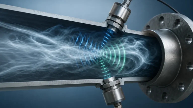
Both radar and ultrasonic sensors utilize the Time-of-Flight principle. The sensor emits a signal (either an electromagnetic wave or a sound wave) that travels to the product surface, reflects, and returns to the receiver. Because the speed of the wave is known, the distance is calculated using the formula:
$$D = \frac{v \cdot t}{2}$$
Where $D$ is the distance, $v$ is the velocity of the wave, and $t$ is the measured time. The level ($L$) is then derived by subtracting this distance from the total tank height ($H$).
Hydrostatic Pressure Principles
Hydrostatic measurement is based on the weight of the liquid column. The pressure ($P$) at the bottom of a tank is directly proportional to the height ($h$) of the liquid, the density ($\rho$) of the liquid, and the gravitational constant ($g$):
$$P = \rho \cdot g \cdot h$$
In applications where the liquid density remains constant, a pressure transmitter at the base of the tank provides a highly accurate continuous level reading.
Buoyancy and Magnetic Coupling
Magnetic level gauges use a float containing a permanent magnet. As the liquid level changes, the float moves along a bypass chamber or a guide tube. This movement is coupled to an external indicator or a resistive/magnetostrictive transmitter that converts the float's position into a continuous electronic signal.
Core Technologies for Continuous Level Monitoring
Industrial applications require different hardware based on the chemical properties of the media, the pressure of the vessel, and the required precision. For a detailed look at specific instrument specifications, engineers can refer to the Main Page of Welk's technical catalog.
1. Radar Level Transmitters
Radar is often considered the gold standard for continuous level measurement due to its versatility.
* Non-contact Radar: These instruments emit high-frequency microwave pulses (often 26GHz or 80GHz). The 80GHz variants are particularly effective because they offer a narrow beam angle, reducing the risk of interference from internal tank structures like agitators or heating coils.
* Guided Wave Radar (GWR): GWR uses a probe (cable or rod) to guide the microwave pulse directly to the surface. This technology is superior in applications with low dielectric constants or where heavy foam and steam are present, as the probe ensures the signal reaches the media.
2. Ultrasonic Level Sensors
Ultrasonic sensors are a cost-effective solution for many water and wastewater applications. They emit high-frequency sound waves. While effective, they are limited by environmental factors; sound speed changes with air temperature, and heavy vapors or dust can attenuate the signal. Most modern ultrasonic units include integrated temperature compensation to mitigate these effects.
3. Hydrostatic Level Transmitters
These are widely used in open reservoirs, deep wells, and vented tanks. Submersible versions are dropped into the liquid, while threaded or flanged versions are mounted to the side of the tank. They are exceptionally reliable but require recalibration if the product density changes significantly (e.g., switching from water to a chemical brine).
4. Magnetic Level Gauges with Transmitters
Magnetic gauges provide both a local visual indication and a continuous remote signal. They are ideal for high-pressure or high-temperature applications where glass gauges would be unsafe. By adding a magnetostrictive transmitter to the outside of the chamber, the system provides a high-resolution continuous level output without contacting the process media directly.
Comparative Selection Criteria for Industrial Applications
Selecting the right technology requires balancing accuracy requirements against the physical constraints of the process. The following table provides a general comparison of the most common continuous level technologies.
| Technology | Media Type | Typical Accuracy | Pressure/Temp Limits | Key Advantage |
| :— | :— | :— | :— | :— |
| 80GHz Radar | Liquids/Solids | ±1 mm | Very High | Non-contact, ignores internal obstructions |
| Guided Wave Radar | Liquids/Slurries | ±2 mm | High | Excellent for low dielectric fluids |
| Ultrasonic | Liquids | ±0.25% of range | Low to Medium | Cost-effective for water treatment |
| Hydrostatic | Liquids | ±0.1% to 0.5% | Medium | Simple installation in deep tanks |
| Magnetic Gauge | Liquids | ±5 mm | High | Visual + Electronic redundancy |
Engineering Installation Guidelines and Best Practices
Proper installation is as critical as selecting the correct technology. Failure to account for the physical environment often leads to signal loss or false readings.
The "Dead Zone" or Blocking Distance
Every Time-of-Flight sensor (Radar and Ultrasonic) has a "dead zone" (also known as a blocking distance) directly beneath the sensor face. In this zone, the sensor cannot accurately process the return signal because it is still in its transmission phase. Typically, this ranges from 10 cm to 50 cm depending on the frequency. Engineers must ensure the maximum fill level of the tank does not enter this zone.
Mounting Position and Beam Angle
For non-contact sensors, the mounting position must avoid the "cone of influence." If a sensor is mounted too close to a wall, the signal may reflect off the wall rather than the media.
* Avoid the center: In round tanks, mounting in the exact center can cause multiple reflections that confuse the processor.
* Avoid the fill stream: Never mount a sensor directly above the point where product enters the tank, as the turbulence and the falling material will cause erratic readings.
Nozzle Considerations
When mounting on a nozzle, the nozzle's height and diameter must be checked against the sensor's beam angle. If the nozzle is too long or narrow, the signal will reflect off the nozzle's interior edges before reaching the tank, creating a "false high" reading.

Common Risks and Technical Limitations
While continuous level technology is advanced, several factors can compromise performance:
1. Foam Interference: Heavy, dense foam can absorb ultrasonic and radar signals. In such cases, Guided Wave Radar is usually the preferred alternative because the probe bypasses the foam's surface attenuation.
2. Vapor and Condensation: High humidity or chemical vapors can slow down sound waves in ultrasonic applications. For radar, condensation on the antenna can cause signal scattering. High-frequency 80GHz radar with a PTFE lens is often used to shed condensation effectively.
3. Agitation and Turbulence: Rapidly moving surfaces can scatter signals. Software filtering (damping) is often required to average the readings, or a stilling well can be installed to provide a calm surface for measurement.
4. Vacuum Conditions: Ultrasonic sensors cannot function in a vacuum because sound waves require a medium (air/gas) to travel. Radar, being electromagnetic, functions perfectly in a vacuum.
Frequently Asked Questions (FAQ)
Q: Can I use one sensor for both liquids and solids?
A: Some radar sensors are designed for both, but solids require a sensor capable of handling "angle of repose" issues, where the material forms a cone. High-power radar with a swiveling flange is usually recommended for solids.
Q: How does dielectric constant affect radar measurement?
A: The dielectric constant ($\epsilon_r$) determines how much energy is reflected back to the sensor. Water has a high dielectric (~80) and is easy to measure. Hydrocarbons have low dielectrics (~2), requiring more sensitive radar or Guided Wave Radar to detect the surface.
Q: Is hydrostatic measurement affected by tank shape?
A: No. Hydrostatic pressure depends only on the height of the liquid and its density, not the volume or shape of the container. However, the conversion of level to volume will require a strapping table or tank linearization software.
Q: What is the maintenance requirement for these sensors?
A: Non-contact radar and ultrasonic sensors are virtually maintenance-free as they have no moving parts. Hydrostatic sensors may require periodic cleaning if the media is prone to coating or buildup on the diaphragm.
Conclusion and Next Steps
Implementing a continuous level system requires a thorough evaluation of the process media, vessel geometry, and environmental conditions. By understanding the underlying physics—whether it is the electromagnetic reflection of radar or the pressure-based calculation of hydrostatic sensors—engineers can select a solution that ensures long-term reliability. For those ready to move from theory to implementation, reviewing specific hardware options on the Main Page will provide the necessary technical data to finalize a system design. Always confirm the chemical compatibility of wetted materials and the electrical classification of the installation site before procurement.