Cooling Tower Sump
Cooling Tower Sump
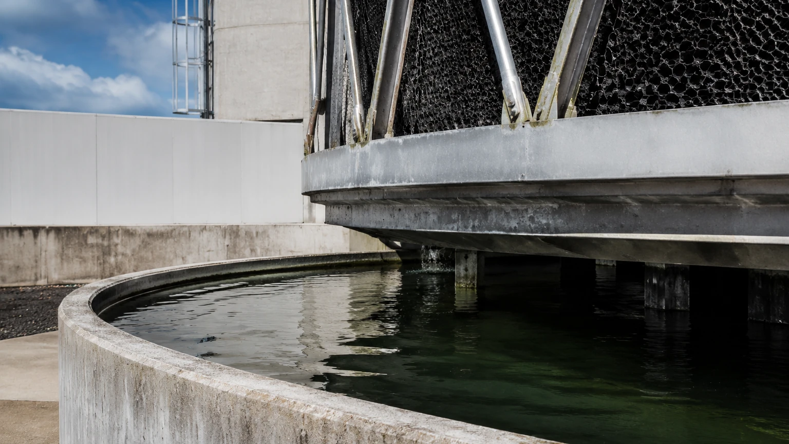
In industrial cooling systems, the cooling tower sump—also known as the cold water basin—serves as the primary reservoir for water that has been cooled and is ready to be recirculated through the heat exchangers or process equipment. While it may appear to be a simple collection tank at the base of the tower, the sump is a critical component that requires precise management to ensure the efficiency, safety, and longevity of the entire cooling loop. Proper level control within the cooling tower sump is essential for preventing pump cavitation, managing chemical concentrations, and avoiding expensive water waste.
Understanding the Role of the Cooling Tower Sump
The cooling tower sump is located at the bottom of the cooling tower structure. Its primary function is to collect the cooled water that falls through the fill media. From this basin, pumps draw the water to send it back into the industrial process.
Because cooling towers operate on the principle of evaporative cooling, water is constantly lost to the atmosphere. This loss, combined with "blowdown" (the intentional drainage of water to remove concentrated minerals), means the sump level is in a state of constant flux. To maintain a steady operation, a make-up water system must replenish the sump. If the level drops too low, the pumps may suck in air, leading to cavitation and mechanical failure. Conversely, if the level is too high, water overflows into the drain, wasting both water and expensive treatment chemicals.
Criticality of Level Measurement in Sump Operations
Effective management of a cooling tower sump relies on accurate, real-time level data. Engineers must monitor several key thresholds:
1. Low-Low Level (L-L): The emergency shut-off point for pumps to prevent dry running.
2. Low Level (L): The trigger point for opening make-up water valves.
3. High Level (H): The trigger point for closing make-up water valves.
4. High-High Level (H-H): An alarm state indicating a potential overflow or valve failure.
Achieving this control requires selecting the right instrumentation based on the specific environmental conditions of the cooling tower, which often include humidity, turbulence, and chemical additives.
Level Measurement Technologies for Cooling Tower Sumps
Before selecting a device, it is important to understand the physics behind the most common measurement principles used in these applications. Welk provides a range of instruments tailored to these specific needs.
Ultrasonic Level Sensors
Ultrasonic sensors are a popular non-contact choice for cooling tower sumps. These devices emit high-frequency sound pulses that travel to the water surface and reflect back to the sensor. The instrument measures the "time-of-flight" to calculate the distance.
* Advantages: No moving parts, easy to install above the water, and generally cost-effective.
* Limitations: Ultrasonic waves can be affected by heavy steam or significant temperature gradients above the water surface. If the cooling tower produces a thick mist, the sound waves may scatter, leading to signal loss.
Radar Level Meters
Radar technology, particularly high-frequency (80GHz) radar, is increasingly replacing ultrasonic sensors in demanding cooling applications. Like ultrasonic sensors, radar is non-contact, but it uses electromagnetic waves instead of sound.
* Advantages: Radar is unaffected by steam, vapor, or air temperature fluctuations. It provides millimeter-level accuracy and can penetrate light foam that might baffle an ultrasonic sensor.
* Limitations: Higher initial cost compared to ultrasonic or hydrostatic options, though the long-term reliability often justifies the investment.
Hydrostatic Level Transmitters
Hydrostatic sensors are contact-based devices that sit at the bottom of the sump or are mounted via a side flange. They measure the pressure exerted by the liquid column above them. Since the density of water is relatively constant, the pressure is directly proportional to the height (Level = Pressure / (Density × Gravity)).
* Advantages: Highly reliable in outdoor environments where wind or surface foam might interfere with top-down sensors. They are simple to integrate into PLC systems.
* Limitations: They are susceptible to errors if the water density changes significantly due to high chemical concentrations, and the sensor head must be cleaned periodically to prevent mineral buildup.
Magnetic Level Gauges and Switches
For localized visual indication or simple point-level control, magnetic gauges and float switches are used. A float containing a magnet moves with the water level, actuating reed switches or moving a visual indicator.
* Advantages: No power required for visual indication; highly reliable for redundant high/low alarms.
* Limitations: Moving parts can become stuck due to scaling or biological growth (algae) common in cooling water.
Selection Criteria for Sump Level Instrumentation
Choosing the right instrument for a cooling tower sump requires an evaluation of the specific site conditions. Engineers should consider the following factors:
* Turbulence: If the water falling from the fill media creates significant splashing, non-contact sensors may require a stilling well to provide a steady reading.
* Chemical Compatibility: Cooling water is treated with biocides, corrosion inhibitors, and anti-scaling agents. Sensor materials (such as PVDF or Stainless Steel) must be resistant to these chemicals.
* Ambient Environment: Since most cooling towers are outdoors, the sensor must have an IP67 or IP68 rating to withstand rain, humidity, and UV exposure.
* Mounting Constraints: Is there a bridge or bracket available for top-down mounting, or is a side-tank connection more feasible?
Practical Selection Table
| Technology | Accuracy | Typical Range | Best Use Case | Maintenance Requirement |
| :— | :— | :— | :— | :— |
| Ultrasonic | ±0.25% | 0.3m – 10m | Standard indoor/outdoor sumps with low steam | Low (Clean sensor face) |
| Radar (80GHz) | ±2mm | 0.1m – 30m | High-precision needs; heavy steam/vapor present | Very Low |
| Hydrostatic | ±0.5% | 0.5m – 20m | Deep sumps; areas with high surface foam | Moderate (Clean diaphragm) |
| Float Switch | N/A (Point) | Fixed | Redundant high/low safety alarms | Moderate (Check for scaling) |
Installation and Maintenance Guidelines
Correct installation is as important as selecting the right technology. For a cooling tower sump, follow these engineering best practices:
1. Avoid the Fill Zone: Never mount a non-contact sensor directly under the water distribution path. The falling water will interfere with the signal. Position the sensor over a relatively calm area of the basin.
2. Use Stilling Wells: In sumps with high turbulence, a stilling well (a vertical pipe with vent holes) can be installed. This creates a calm surface for ultrasonic or radar sensors and protects hydrostatic probes from lateral movement.
3. Dead Zone Awareness: All top-down sensors have a "dead zone" (blocking distance) near the sensor face where they cannot measure. Ensure the sensor is mounted high enough so that the maximum water level never enters this zone.
4. Grounding and Shielding: To prevent interference from large cooling tower fan motors, ensure all instrumentation cabling is shielded and properly grounded.
5. Regular Cleaning: Cooling tower environments are prone to mineral scaling and biological fouling. Periodically inspect sensors for calcium deposits or algae growth, which can foul diaphragms or block ultrasonic signals.
Common Risks and Limitations
While modern instrumentation is robust, the cooling tower sump environment presents unique challenges:
* Foaming: Over-treatment with certain chemicals can cause foam. Ultrasonic sensors may see the top of the foam as the water level, while radar and hydrostatic sensors typically see through it to the actual liquid.
* Wind Interference: In very large, open sumps, strong winds can push water to one side, causing a false low reading on one end and a potential overflow on the other. In such cases, averaging the signal from two sensors may be necessary.
* Scaling: High mineral content in the recirculating water can lead to "bridging" on mechanical switches. Non-contact sensors are generally preferred to minimize this risk.
Frequently Asked Questions (FAQs)
Q: Can I use a standard pressure transmitter for sump level?
A: Yes, provided it is a hydrostatic level transmitter designed for immersion or has a chemical-resistant diaphragm. Standard industrial pressure transmitters may corrode if not rated for the specific water treatment chemicals used.
Q: Why is my ultrasonic sensor giving erratic readings when the fans are on?
A: This is likely due to air turbulence or steam. When the fans are active, they create a high-velocity air stream and can pull steam down toward the sump. Switching to a radar sensor usually resolves this issue as radar is not affected by air movement or vapor.
Q: How do I prevent the make-up water valve from "chattering"?
A: This occurs when the water surface is wavy, causing the sensor to flip-flop between high and low signals. You can solve this by increasing the "damping" or "integration time" in the sensor settings or by implementing a deadband (hysteresis) in your control logic.
Conclusion
The cooling tower sump is the heartbeat of the industrial cooling process. Ensuring its level is monitored with precision is a fundamental requirement for operational stability. By understanding the strengths and limitations of ultrasonic, radar, and hydrostatic technologies, engineers can select a solution that minimizes maintenance and maximizes system uptime. For more detailed technical specifications and to explore a wide range of industrial measurement tools, visit the Main Page to review product options and application support from Welk.