Diesel Tank Level Sensor
Diesel Tank Level Sensor
In industrial and commercial operations, diesel fuel serves as the lifeblood for backup power systems, heavy machinery, and logistical fleets. Monitoring the volume within storage vessels is not merely a matter of inventory management but a critical safety and operational requirement. A reliable diesel tank level sensor ensures that fuel is available when needed, prevents hazardous overfills, and detects potential leaks or unauthorized usage.
Selecting the appropriate technology for diesel measurement requires an understanding of the physical properties of the fuel, the geometry of the storage tank, and the environmental conditions of the installation site. This guide provides a technical overview of the primary measurement principles, selection criteria, and installation best practices for diesel level monitoring.
Measurement Principles for Diesel Fuel
Diesel is a hydrocarbon liquid with specific characteristics that influence sensor performance, including a relatively low dielectric constant (typically 2.0 to 2.2), a density of approximately 832 kg/m³, and a flash point that necessitates explosion-proof hardware in many jurisdictions. Several technologies are commonly employed to measure these levels.
Radar Level Measurement
Radar sensors are widely considered the gold standard for diesel applications due to their non-contact nature and high precision. They operate on the Time-of-Flight (ToF) principle, emitting electromagnetic pulses that travel at the speed of light. These pulses reflect off the surface of the diesel and return to the sensor.
* Non-Contact Radar: Modern 80GHz radar transmitters offer a narrow beam angle, which is ideal for avoiding internal tank obstructions like ladders or heating coils. Because radar waves are unaffected by temperature fluctuations or the presence of diesel vapors in the headspace, they provide highly stable readings.
* Guided Wave Radar (GWR): GWR uses a physical probe (rod or cable) to guide the microwave pulse to the liquid surface. This is particularly effective for diesel because the probe concentrates the energy, ensuring a strong return signal even from low-dielectric liquids. GWR is often preferred for smaller tanks or those with turbulent surfaces.
Ultrasonic Level Sensors
Ultrasonic sensors also use the ToF principle but utilize sound waves instead of electromagnetic pulses. The sensor emits a high-frequency sound burst that reflects off the fuel surface. The time taken for the echo to return is proportional to the distance to the liquid.
While cost-effective, ultrasonic sensors have limitations in diesel applications. The speed of sound is affected by air temperature and the composition of the gas in the tank's headspace. Since diesel evaporates, the concentration of vapors can slightly alter the measurement accuracy. Most high-quality ultrasonic sensors include integrated temperature compensation to mitigate these effects.
Hydrostatic Level Transmitters
Hydrostatic sensors measure the pressure exerted by the column of liquid above the sensor diaphragm. The relationship is defined by the formula: $P = \rho gh$, where $P$ is pressure, $\rho$ is the density of the diesel, $g$ is gravity, and $h$ is the height of the liquid.
For diesel tanks, these sensors are typically either submersible (lowered to the bottom of the tank) or externally mounted via a flange or threaded connection at the tank's base. Because diesel density changes with temperature, hydrostatic systems often require a temperature-compensated transmitter or a secondary temperature probe to maintain accuracy across seasonal shifts.
Magnetic Level Gauges
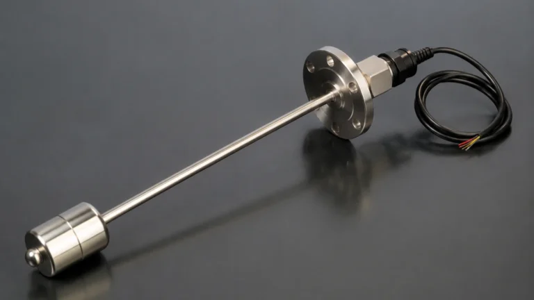
Magnetic level gauges are used when both a local visual indication and a remote signal are required. A float containing a permanent magnet moves with the diesel level inside a bypass chamber or directly within the tank. Outside the chamber, a series of magnetic flags flip to show the level, and a reed-chain or magnetostrictive transmitter can be attached to provide a 4-20mA or digital output.
Key Evaluation Criteria for Selection
Choosing the right diesel tank level sensor involves balancing technical requirements with budget constraints. Engineers should evaluate the following factors:
1. Tank Geometry and Placement: Underground storage tanks (UST) often favor submersible hydrostatic sensors or GWR due to limited headspace. Above-ground storage tanks (AST) provide more flexibility for non-contact radar or ultrasonic units.
2. Accuracy Requirements: For custody transfer or high-value inventory, radar offers the highest precision (often $\pm$1mm to $\pm$3mm). For general monitoring of a backup generator tank, ultrasonic or hydrostatic sensors with $\pm$0.5% FS accuracy are usually sufficient.
3. Environmental Conditions: If the tank is located in an area with extreme temperature swings, radar is superior because its signal is independent of air density and temperature.
4. Hazardous Area Certification: Since diesel is flammable, sensors must often comply with ATEX, IECEx, or UL standards for Class I, Div 1 or Div 2 environments.
5. Output and Integration: Most industrial sensors provide a 4-20mA signal with HART protocol, though Modbus RTU is increasingly common for integration into building management systems (BMS) or IoT gateways.
For a comprehensive look at available measurement technologies and technical specifications, professionals can refer to the Main Page of industrial instrumentation providers to compare model-specific data.
Technical Selection Table
| Technology | Contact Type | Accuracy | Typical Range | Key Advantage | Limitation |
| :— | :— | :— | :— | :— | :— |
| 80GHz Radar | Non-contact | $\pm$1-2 mm | Up to 30m+ | Unaffected by vapors/temp | Higher initial cost |
| Guided Wave Radar | Contact | $\pm$2-5 mm | Up to 20m | Excellent for low dielectric | Probe can catch debris |
| Ultrasonic | Non-contact | $\pm$0.25-0.5% | 0.25m – 15m | Cost-effective | Affected by heavy vapors |
| Hydrostatic | Contact | $\pm$0.1-0.5% | 1m – 200m | Simple installation | Density dependent |
| Magnetic Gauge | Contact | $\pm$5-10 mm | 0.5m – 6m | Visual + Electronic | Moving parts (float) |
Installation Considerations
Proper installation is as vital as sensor selection. Even the most advanced radar unit will fail to provide accurate data if installed incorrectly.
Avoiding Obstructions
For non-contact sensors (Radar and Ultrasonic), the "beam" must have a clear path to the liquid surface. Avoid mounting the sensor near the tank wall, as side-wall reflections can create "ghost" signals. Similarly, ensure the sensor is not positioned directly above an inlet pipe, as the turbulence from filling will cause erratic readings.
The Dead Zone (Blocking Distance)
All top-mounted sensors have a "dead zone" or "blocking distance" directly beneath the sensor face where measurement is impossible. For ultrasonic sensors, this is typically 0.2m to 0.5m. For radar, it is much smaller, often less than 0.1m. It is crucial to ensure the tank's maximum fill level does not enter this zone.
Pressure and Vacuum Relief
Diesel tanks are often vented to the atmosphere. However, in pressurized systems, the sensor must be rated for the operating pressure. Furthermore, if a vacuum is pulled during rapid fuel extraction, the sensor diaphragm (in hydrostatic models) must be robust enough to withstand the reverse pressure.
Grounding and Shielding
In industrial environments, electrical noise from pumps and motors can interfere with low-voltage sensor signals. Using shielded twisted-pair cabling and ensuring the sensor housing is properly grounded is essential for signal integrity.
Limitations and Common Risks
While modern sensors are highly reliable, certain factors can compromise diesel level measurement:
* Paraffin Wax Buildup: In extremely cold climates, diesel can "cloud" as paraffin waxes precipitate. This can coat the probes of GWR sensors or the diaphragms of hydrostatic sensors, leading to sluggish response or offset errors.
* Foaming: During high-speed filling, diesel can foam. Ultrasonic sensors may struggle with foam as it absorbs sound waves, whereas radar can typically penetrate light foam or reflect off the top of it.
* Water Bottoms: Diesel tanks often accumulate a layer of water at the bottom due to condensation. Hydrostatic sensors measure the total pressure, so they cannot distinguish between water and diesel. If a water-diesel interface measurement is required, Guided Wave Radar with interface capabilities should be used.
Frequently Asked Questions (FAQ)
Q: Can I use an ultrasonic sensor for an underground diesel tank?
A: Yes, provided the tank is vented and the sensor is mounted in a way that the dead zone is accounted for. However, if the tank is deep and narrow, a hydrostatic transmitter or GWR is often easier to install.
Q: How does diesel density affect my level reading?
A: Density only significantly affects hydrostatic sensors. If the diesel temperature increases, it expands and its density decreases. A hydrostatic sensor will see less pressure and report a lower level even if the volume remains the same. Radar and ultrasonic sensors are not affected by density changes.
Q: Is a diesel tank level sensor maintenance-free?
A: Non-contact sensors like radar are nearly maintenance-free as they have no moving parts and do not touch the fuel. Submersible sensors should be checked periodically for sludge or bio-growth buildup on the diaphragm.
Q: What signal output should I choose for a remote generator site?
A: For remote sites, a 4-20mA signal is standard for long-distance transmission (up to 1,000m). If you are using an IoT gateway, Modbus RTU is often preferred as it can transmit multiple variables (level, temperature, and diagnostics) over a single pair of wires.
Conclusion
Implementing a robust diesel tank level sensor system is a foundational step in modern industrial asset management. By understanding the measurement principles—from the high-precision capabilities of 80GHz radar to the rugged simplicity of hydrostatic transmitters—engineers can select a solution that minimizes risk and maximizes operational efficiency. Always confirm the specific chemical compatibility and hazardous area requirements of your site before finalizing an instrument selection to ensure long-term reliability and safety.