Differential Pressure Transducer Calibration
Differential Pressure Transducer Calibration
In the landscape of industrial automation and process control, differential pressure (DP) transducers serve as the backbone for various critical measurements, including fluid flow, liquid level, and filter monitoring. However, the reliability of these measurements is entirely dependent on the accuracy of the instrument. Over time, environmental factors, mechanical stress, and electronic drift can compromise the precision of a sensor. This makes differential pressure transducer calibration an essential maintenance task for engineers and technicians seeking to ensure process safety and efficiency.
Calibration is the process of comparing the output of a measurement device against a traceable reference standard and adjusting the device to minimize errors. For DP transducers, this involves applying known pressures to the high and low ports and verifying that the electrical output (typically 4-20 mA or a digital signal) aligns with the expected values. This guide explores the principles, procedures, and technical considerations necessary for effective calibration in industrial environments.
Principles of Differential Pressure Measurement
Before delving into the specifics of calibration, it is vital to understand how a differential pressure transducer functions. At its core, the device contains a sensing element—often a diaphragm—that separates two pressure chambers: the High-Pressure (H) side and the Low-Pressure (L) side.
When pressure is applied, the diaphragm deflects toward the side with lower pressure. This physical displacement is converted into an electrical signal through various technologies, such as piezoresistive strain gauges, capacitive sensors, or LVDTs (Linear Variable Differential Transformers). The fundamental equation governing this measurement in level applications is:
$$\Delta P = P_{high} – P_{low} = \rho · g · h$$
Where:
* ·ρ (Rho): The density of the fluid (kg/m³).
* g: The acceleration due to gravity (approximately 9.81 m/s²).
* h: The height of the liquid column (meters).
In flow applications, the transducer measures the pressure drop across a primary flow element like an orifice plate or Venturi tube, where the flow rate is proportional to the square root of the differential pressure. Because these relationships are mathematical, any deviation in the transducer's ability to sense $\Delta P$ accurately results in significant errors in the calculated level or flow rate.
The Importance of Differential Pressure Transducer Calibration
Industrial environments are harsh. Transducers are subjected to temperature fluctuations, vibrations, overpressure events, and chemical exposure. These factors contribute to "sensor drift," where the relationship between the input pressure and the output signal changes over time.
Why Calibrate?
1. Regulatory Compliance: Many industries, such as pharmaceuticals and food processing, require documented proof that instruments are operating within specified tolerances to meet safety and quality standards.
2. Process Efficiency: Inaccurate level readings in a chemical reactor can lead to suboptimal reactions or dangerous overflows. Precise calibration ensures that raw materials are utilized efficiently.
3. Safety: In pressurized vessels, accurate DP measurement is critical for preventing overpressure conditions that could lead to equipment failure.
4. Economic Accountability: In custody transfer applications, where fluids are bought or sold based on flow measurements, a small calibration error can result in significant financial discrepancies.
Calibration Procedures and Equipment
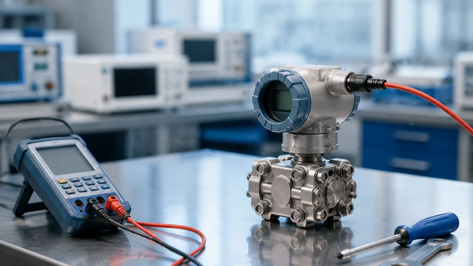
Performing a differential pressure transducer calibration requires a controlled environment or specialized field equipment. The goal is to perform a "five-point check," testing the device at 0%, 25%, 50%, 75%, and 100% of its calibrated span.
Required Equipment
* Pressure Source: A hand pump or a deadweight tester capable of generating stable pressure.
* Reference Standard: A high-precision digital pressure gauge (calibrator) with an accuracy at least four times better than the device under test (DUT).
* Multimeter or Loop Calibrator: To measure the 4-20 mA output signal.
* Power Supply: Usually a 24V DC source to power the transducer loop.
* Manifold: A 3-valve or 5-valve manifold to isolate the transducer from the process and equalize pressure during zeroing.
Step-by-Step Calibration Process
1. Isolation and Equalization: Close the process valves and open the equalizing valve on the manifold. This ensures both the High and Low sides see the same pressure (atmospheric), allowing for an accurate "Zero" check.
2. Zero Trim: With the pressure equalized, the output should be exactly 4.000 mA. If it deviates, a "Zero Trim" is performed via the instrument's software or adjustment screws.
3. Applying Pressure (Span): Close the equalizing valve and apply the maximum rated pressure for the specific application to the High-Pressure port while leaving the Low-Pressure port vented to the atmosphere (for gauge-referenced DP).
4. Five-Point Verification: Gradually increase the pressure in increments (0, 25, 50, 75, 100% of span) and record the mA output at each stage. Then, decrease the pressure through the same points to check for hysteresis (the difference in readings when approaching a point from above versus below).
5. Adjusting the Span: If the 100% point does not yield 20.000 mA, a "Span Trim" is required. Note that modern smart transmitters often require digital adjustment using HART or Foundation Fieldbus protocols.
Selection Criteria for DP Transducers
Choosing the right instrument is the first step in minimizing the frequency of calibration. The following table provides a reference for selecting transducers based on common industrial requirements.
| Application | Pressure Range | Accuracy (Standard) | Wetted Materials | Recommended Technology |
| :— | :— | :— | :— | :— |
| Water Tank Level | 0 – 500 mbar | ±0.1% | 316L Stainless Steel | Piezoresistive |
| Chemical Storage | 0 – 2 bar | ±0.075% | Hastelloy C / PTFE | Capacitive |
| Steam Flow | 0 – 5 bar | ±0.05% | Monel / 316 SS | High-Temp Differential |
| Oil & Gas Pipelines | 0 – 100 bar | ±0.04% | Super Duplex | Multi-variable DP |
For a comprehensive look at available measurement technologies, engineers should Review product options and application support to match sensor specifications with process conditions.
Installation Considerations for Optimal Accuracy
Calibration is only effective if the transducer is installed correctly. Poor installation can introduce "induced errors" that calibration cannot fix.
Impulse Line Routing
Impulse lines (the tubes connecting the process to the transducer) must be installed to prevent gas pockets in liquid lines or liquid traps in gas lines.
* For Liquids: The transducer should be mounted below the process taps so that air bubbles rise back into the process pipe.
* For Gases: The transducer should be mounted above the process taps so that any condensate drains back into the pipe.
* Slope: A minimum slope of 1:12 (8%) is recommended for impulse piping to ensure proper drainage or venting.
Mounting and Orientation
DP transducers are sensitive to orientation because the weight of the internal fill fluid can exert pressure on the diaphragm. If a transducer is calibrated in a horizontal position but installed vertically, a zero shift will occur. Always perform a zero trim *after* the final installation to account for mounting position and static pressure effects.
Manifold Usage
A 5-valve manifold is preferred for high-pressure applications. It includes two block valves, two vent valves, and one equalizer valve. This setup allows the technician to bleed off trapped pressure and safely perform field checks without removing the instrument from the line.
Limitations and Common Challenges
While DP transducers are versatile, they have inherent limitations that can complicate the calibration process:
1. Static Pressure Effect: Many DP sensors exhibit a shift in their zero point when subjected to high static (line) pressure, even if the differential pressure is zero. Calibration should ideally be verified at the actual operating static pressure.
2. Temperature Sensitivity: Changes in ambient temperature affect the density of the fill fluid inside the capillary tubes or the sensor body. While most modern units have internal temperature compensation, extreme fluctuations may still require periodic re-zeroing.
3. Hysteresis and Repeatability: If the transducer fails to return to 4 mA after a full-scale pressure cycle, the sensing diaphragm may be damaged or fatigued. In such cases, the unit must be replaced rather than recalibrated.
4. Specific Gravity Changes: In level measurement, if the density (ρ) of the liquid changes (due to temperature or composition changes), the DP reading will change even if the physical level remains constant. This is a process limitation, not a transducer error, but it is often mistaken for a calibration issue.
Frequently Asked Questions (FAQs)
Q: How often should I calibrate my differential pressure transducer?
A: The frequency depends on the criticality of the process and the stability of the environment. A standard interval is 12 to 24 months, but high-precision or safety-critical applications may require semi-annual checks.
Q: What is the difference between a "Zero Trim" and a "Reranging"?
A: A Zero Trim corrects the sensor's internal reading to match a zero-pressure condition. Reranging (or spanning) changes the 4 mA and 20 mA points to correspond to different physical pressures without necessarily changing the sensor's base calibration.
Q: Can I calibrate a DP transducer using a column of water?
A: Yes, for low-pressure ranges, a water column (manometer) provides a very accurate primary standard. However, for higher pressures, a digital pressure calibrator or deadweight tester is more practical and safer.
Q: What is "Wet Leg" vs. "Dry Leg" in DP level measurement?
A: A "Dry Leg" is used when the space above the liquid is filled with a non-condensing gas. A "Wet Leg" is used when the gas might condense; the low-pressure impulse line is intentionally filled with a reference liquid to prevent erratic readings. Calibration must account for the constant hydrostatic head of the wet leg.
Conclusion
Mastering differential pressure transducer calibration is a fundamental skill for maintaining the integrity of industrial process data. By understanding the underlying physics of the measurement, employing the correct tools, and following a rigorous five-point verification process, technicians can ensure that their level and flow systems operate within their designed tolerances.
When selecting new instrumentation, it is essential to consider not only the initial accuracy but also the long-term stability and ease of calibration. For professional-grade hardware and expert guidance on selecting the right level measurement solutions for your specific industry, visit the Welk Main Page to explore a wide range of radar, ultrasonic, and hydrostatic instruments designed for modern industrial automation.
Download Differential Pressure Transducer Calibration as a PDF