Profibus
Profibus
In the landscape of industrial automation and process control, the ability to transmit accurate data from field instruments to a central control system is paramount. Profibus (Process Field Bus) remains one of the most established and widely adopted fieldbus standards globally. For engineers and system integrators specializing in level measurement, understanding how Profibus integrates with technologies such as radar, ultrasonic, and hydrostatic sensors is essential for building robust, scalable, and efficient industrial networks.
As a professional manufacturer of industrial level measurement instruments, Welk provides a range of solutions that leverage digital communication protocols to ensure high-precision data acquisition. This guide explores the technical nuances of Profibus, its application in level measurement, and the practical considerations for field implementation.
Understanding the Principles of Level Measurement
Before diving into the communication protocol, it is necessary to understand the underlying measurement principles of the instruments that generate the data. In a Profibus network, the field instrument acts as the data source. The accuracy of the entire system depends on the physics of the sensor.
Radar Level Measurement
Radar level meters, such as those produced by Welk, utilize either Pulse Radar or Frequency Modulated Continuous Wave (FMCW) technology. These instruments emit high-frequency electromagnetic waves (typically in the 26 GHz or 80 GHz range) toward the medium. The waves reflect off the surface and return to the sensor. By measuring the time-of-flight or the frequency shift, the device calculates the distance to the product surface. Radar is preferred for its non-contact nature and its ability to operate effectively in high-pressure (up to 40 bar / 580 psi) and high-temperature environments.
Ultrasonic Level Sensors
Ultrasonic sensors function by emitting sound waves at frequencies above the human hearing range. The sensor measures the time taken for the echo to return from the liquid or solid surface. While highly cost-effective, ultrasonic measurement is sensitive to air temperature, turbulence, and heavy foam. It is most commonly used in water treatment and open-channel flow applications.
Hydrostatic Level Transmitters
Hydrostatic measurement relies on the principle that the pressure at a specific depth in a liquid is proportional to the height of the liquid column above it. A pressure sensor at the bottom of a tank measures this "head pressure." This method is highly reliable for vented tanks and deep wells, provided the density of the liquid remains constant.
The Role of Profibus in Level Measurement
Profibus provides the digital bridge between these physical sensors and the Programmable Logic Controller (PLC) or Distributed Control System (DCS). Unlike traditional 4-20 mA analog signals, which only transmit a single process variable, Profibus allows for the transmission of multiple parameters, diagnostic data, and configuration settings over a single pair of wires.
There are two primary versions of Profibus used in industrial level measurement: Profibus DP and Profibus PA.
Profibus DP (Decentralized Periphery)
Profibus DP is designed for high-speed data exchange. It typically operates over an RS-485 physical layer and can reach speeds up to 12 Mbps. In level measurement, Profibus DP is often used to connect remote I/O stations or sophisticated transmitters located in non-hazardous areas where rapid response times are critical.
Profibus PA (Process Automation)
Profibus PA is specifically tailored for the process industries. It utilizes the MBP (Manchester Coded, Bus Powered) physical layer, which allows both power and data to be delivered over the same two wires. Crucially, Profibus PA is designed for use in explosion-hazardous areas (Ex-zones). It operates at a fixed speed of 31.25 kbit/s, which is optimized for stability over long distances and compatibility with intrinsic safety requirements.
Technical Selection Criteria
Choosing the right Profibus interface for a level measurement project requires an evaluation of the environment, the required data throughput, and the physical layout of the plant. The following table provides a comparison for selection purposes:
| Feature | Profibus DP | Profibus PA |
| :— | :— | :— |
| Primary Application | Factory automation, high-speed I/O | Process automation, chemical plants |
| Physical Layer | RS-485 | MBP (IEC 61158-2) |
| Data Rate | 9.6 kbps to 12 Mbps | Fixed 31.25 kbps |
| Bus Power | No (Separate power required) | Yes (Power over signal wires) |
| Hazardous Area Use | Limited (Requires isolation) | Optimized (Intrinsically Safe) |
| Topology | Line (Bus) | Line, Tree, or Star |
| Max Segment Length | 100m to 1200m (depends on speed) | Up to 1900m (6233 ft) |
When selecting a level meter from the Welk product line, engineers must confirm if the integration requires the high speed of DP or the bus-powered, intrinsically safe characteristics of PA. For detailed product specifications and protocol support, you can visit the Main Page to review available options.
Installation and Configuration Guidelines
Successful implementation of a Profibus-based level measurement system depends heavily on correct physical installation and software configuration. Errors in wiring or addressing are the leading causes of commissioning delays.
Segment Design and Length
For Profibus PA, the maximum segment length is 1900 meters (approx. 6233 feet). This includes the length of all trunks and spurs. If the segment exceeds this length, or if the total current draw of the connected level meters exceeds the power supply capacity, repeaters or additional segments must be used. For Profibus DP, the maximum length is inversely proportional to the baud rate; for example, at 1.5 Mbps, the segment is limited to 200 meters (656 feet) without repeaters.
Cable Specifications
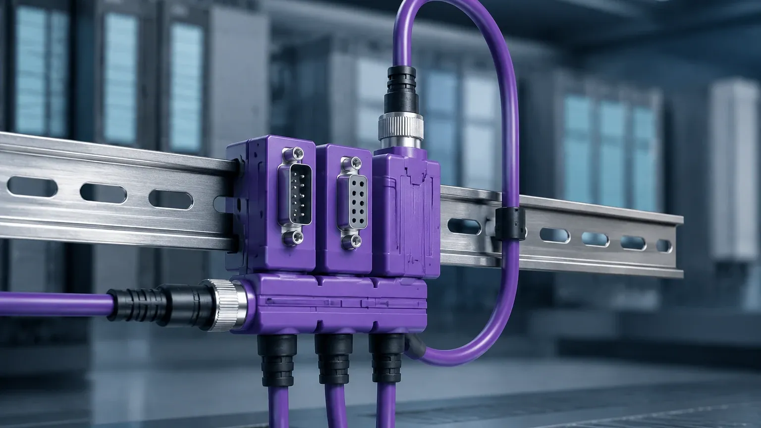
Only shielded twisted-pair cables specifically rated for Profibus should be used. Type A cable is the standard recommendation. Improper cable selection can lead to signal attenuation and electromagnetic interference (EMI), resulting in intermittent data loss from the level sensors.
Termination
Both ends of a Profibus DP segment must be terminated with an active terminator to prevent signal reflection. In Profibus PA, an RC (Resistor-Capacitor) terminator is required at both ends of the bus. Failure to terminate correctly is a frequent cause of "bus jitters" and communication errors.
GSD Files
Every Profibus device has a General Station Description (GSD) file provided by the manufacturer. This file contains the device's capabilities, including supported baud rates and data structures. Before commissioning a Welk level meter on a Profibus network, the corresponding GSD file must be imported into the PLC configuration tool (such as Siemens TIA Portal or Step 7).
Limitations and Common Risks
While Profibus is a robust technology, it is not without limitations. Project managers should be aware of the following risks:
1. Addressing Conflicts: Each device on a Profibus segment must have a unique address (0-126). Duplicate addresses will cause the bus to fail. It is standard practice to set addresses via hardware switches or software before connecting the device to a live network.
2. Power Limitations (PA): In Profibus PA networks, the number of devices per segment is limited by the current consumption of each transmitter. A typical level meter may draw 10-15 mA. If the bus power supply is rated for 500 mA, one must account for the safety margin and cable resistance when calculating the maximum number of devices.
3. Sensitivity to Noise: Although shielded cable is used, running Profibus lines parallel to high-voltage power cables or near Variable Frequency Drives (VFDs) without proper separation can induce noise that disrupts digital communication.
4. Protocol Obsolescence: While Profibus remains widely used, many new installations are moving toward Profinet (Industrial Ethernet). Engineers should evaluate whether the project requires the legacy stability of Profibus or the higher bandwidth of Profinet.
Maintenance and Troubleshooting
Maintaining a Profibus level measurement system involves periodic checks of signal quality. Modern diagnostic tools can measure the "health" of the bus, identifying issues like weak signal levels or excessive noise before they cause a system shutdown.
If a level meter stops communicating, the first step is to check the status LEDs on the device. Most Welk instruments include diagnostic indicators. If the device is powered but not communicating, verify the termination and check for physical damage to the cable. In Profibus PA systems, verify that the voltage at the furthest device is at least 9V DC.
Frequently Asked Questions (FAQ)
Q: Can I mix Profibus DP and PA on the same cable?
No. They use different physical layers and data rates. To connect Profibus PA instruments to a Profibus DP master, a DP/PA Coupler or Link is required.
Q: How many level meters can I connect to a single Profibus PA segment?
Technically, up to 32 devices can be connected, but in practice, this is usually limited to 10-12 devices in intrinsically safe (Ex) applications due to power constraints.
Q: Do Welk level meters support the Profile 3.0 standard?
Yes, most modern digital level transmitters follow the Profibus Profile for Process Control Devices, which ensures interchangeability and standardized data structures for process variables and diagnostics.
Q: What is the difference between a GSD file and a DTM?
A GSD file is used for basic cyclic data exchange (getting the level reading into the PLC). A DTM (Device Type Manager) is used for more complex acyclic communication, such as remote calibration and viewing diagnostic echo curves via FDT frame applications.
Conclusion
Profibus continues to be a cornerstone of industrial communication, providing the reliability and precision required for demanding level measurement tasks. By understanding the differences between DP and PA variants and adhering to strict installation standards regarding cabling, termination, and addressing, engineers can ensure that their Welk level measurement instruments provide accurate, real-time data for years to come. For technical support in selecting the appropriate instrument for your specific application, please refer to the product documentation on our Main Page.