Differential Sensors
Differential Sensors
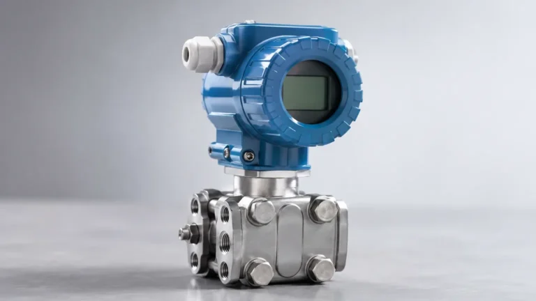
In the landscape of industrial process control, the ability to accurately determine the volume or height of a liquid within a vessel is fundamental to safety and efficiency. Among the various technologies available, differential sensors—specifically differential pressure (DP) transmitters—remain a cornerstone for level measurement in both vented and pressurized tanks. By measuring the pressure difference between two distinct points, these instruments provide a reliable calculation of liquid head, even when the internal environment of the tank is subject to significant static pressure.
Measurement Principles of Differential Sensors
The fundamental principle underlying the use of differential sensors for level measurement is hydrostatic pressure. According to Pascal’s Law, the pressure exerted by a static liquid column is directly proportional to its height and the density of the fluid. The mathematical relationship is expressed as:
P = ρ · g · h
Where:
* P is the hydrostatic pressure.
* ρ (rho) is the fluid density (kg/m³).
* g is the local acceleration due to gravity (approximately 9.81 m/s²).
* h is the height of the liquid column (meters).
In an open, vented tank, a simple pressure sensor at the bottom can measure the liquid level because the top of the liquid is at atmospheric pressure. However, in closed industrial vessels, the space above the liquid is often filled with pressurized gas or vapor. A single-point pressure sensor would measure the sum of the liquid head and the gas pressure, leading to an incorrect level reading.
Differential sensors solve this by utilizing two sensing elements. The "High Pressure" (HP) side is connected to the bottom of the tank, while the "Low Pressure" (LP) side is connected to the top (gas space). The sensor subtracts the gas pressure from the total pressure at the bottom, isolating the pressure exerted solely by the liquid column. This resulting differential pressure is then converted into a linear 4-20mA signal or digital output representing the level.
Practical Configurations: Wet Leg vs. Dry Leg
When implementing differential sensors, engineers must choose between different piping configurations based on the characteristics of the gas or vapor in the tank headspace.
1. Dry Leg Configuration
This setup is used when the gas in the headspace is non-condensing under all operating conditions (e.g., dry nitrogen or air). The LP impulse line remains filled with gas. Because the weight of the gas in the vertical line is negligible, the sensor accurately reflects the liquid level without additional compensation.
2. Wet Leg Configuration
If the gas in the headspace is a vapor that can condense into a liquid (such as steam), a dry leg would eventually fill with condensate, leading to erratic readings. In this case, the LP impulse line is intentionally filled with a reference liquid (often the process fluid or a stable buffer liquid). This is known as a "wet leg." Because the LP side now has a constant liquid head, the transmitter must be calibrated with a "Zero Suppression" or "Zero Elevation" offset to account for the weight of the reference column.
3. Remote Diaphragm Seals
For corrosive, viscous, or high-temperature media that might clog or damage standard impulse lines, differential sensors are often equipped with remote seals. These consist of a flexible diaphragm connected to the transmitter via oil-filled capillary tubes. The pressure is transmitted through the oil, keeping the process media isolated from the sensor electronics.
Selection Criteria for Industrial Applications
Choosing the correct differential sensors requires a detailed understanding of the process environment. The following table provides a selection framework for common industrial scenarios:
| Application Requirement | Recommended Configuration | Material/Feature Consideration |
| :— | :— | :— |
| Clean, non-corrosive water | Standard DP Transmitter | 316 Stainless Steel diaphragms |
| Pressurized steam boiler | Wet Leg Configuration | Condensate pot required for stability |
| Corrosive chemicals (Acids) | Remote Diaphragm Seals | Tantalum or PTFE-coated diaphragms |
| High-viscosity fluids | Flush Diaphragm Seal | Prevents media buildup in ports |
| Hygienic/Food & Beverage | Sanitary Remote Seals | Tri-clamp connections; food-grade fill oil |
When evaluating hardware, it is essential to consult a professional manufacturer to ensure the pressure range (span) and static pressure rating of the device align with the vessel's maximum operating limits. For more detailed technical specifications, you can visit the Main Page of our product catalog.
Installation Considerations and Best Practices
The accuracy of differential sensors is highly dependent on the quality of the installation. Even the most advanced sensor will provide false data if the impulse lines or mounting positions are incorrect.
1. Impulse Line Slope: To prevent gas bubbles from being trapped in liquid lines (or liquid from trapping in gas lines), impulse piping should be sloped at a minimum of 1:12 (8%). For liquid measurement, the transmitter should ideally be mounted below the process taps so that air bubbles can rise back into the tank.
2. Manifold Valves: A 3-valve or 5-valve manifold should always be installed between the process and the sensor. This allows for safe isolation, venting, and zero-point calibration without shutting down the entire process.
3. Temperature Stability: If using capillary-based remote seals, both capillaries should be kept at the same temperature. Significant temperature differences between the HP and LP capillaries can cause the fill oil to expand unevenly, resulting in a "temperature drift" error.
4. Mounting Position: The physical elevation of the transmitter relative to the bottom tap must be accounted for during commissioning. If the transmitter is mounted 1 meter below the bottom tap, the constant liquid head in the tubing must be electronically subtracted (zero suppression).
Limitations and Potential Risks
While differential sensors are versatile, they are not "set and forget" devices. Users must be aware of the following limitations:
* Density Sensitivity: Since DP sensors measure weight to infer height, any change in the liquid's density (caused by temperature fluctuations or changes in chemical composition) will result in an error. If the density decreases by 5%, the reported level will also be 5% lower than the actual height.
* Clogging: Impulse lines are susceptible to plugging if the process fluid contains solids or tends to crystallize. Regular flushing or the use of remote seals is necessary in these environments.
* Static Pressure Limits: Every differential sensor has a maximum static pressure rating. Exceeding this can deform the internal sensing element, leading to permanent shift or failure.
Frequently Asked Questions (FAQ)
Q: How often should differential sensors be calibrated?
A: In standard applications, an annual calibration check is recommended. However, in high-precision or safety-critical environments (such as custody transfer or chemical reactors), semi-annual checks may be required. Modern "Smart" transmitters often have internal diagnostics that can alert operators to potential drift.
Q: Can a differential pressure sensor be used for interface measurement?
A: Yes. If two immiscible liquids (like oil and water) are in the same tank, a DP sensor can measure the level of the interface, provided the total liquid level remains constant and the densities of both fluids are known and stable.
Q: What is the difference between a pressure transmitter and a differential pressure transmitter?
A: A standard pressure transmitter has one process connection and measures pressure relative to the atmosphere (gauge pressure). A differential pressure transmitter has two connections and measures the specific difference between them, making it suitable for pressurized tanks and flow measurement.
Conclusion
Differential sensors remain a primary choice for industrial level measurement due to their robustness and lack of moving parts. By understanding the relationship between hydrostatic pressure and fluid density, and by selecting the appropriate wet leg or remote seal configuration, engineers can achieve highly accurate results in challenging process conditions. Successful implementation requires careful attention to impulse line routing, zero suppression, and the physical properties of the media. For those seeking reliable, cost-effective level measurement solutions tailored to specific industrial automation needs, reviewing the comprehensive options available on our Main Page is a recommended next step in the engineering process.