
Digital Differential Pressure Sensor
Digital Differential Pressure Sensor
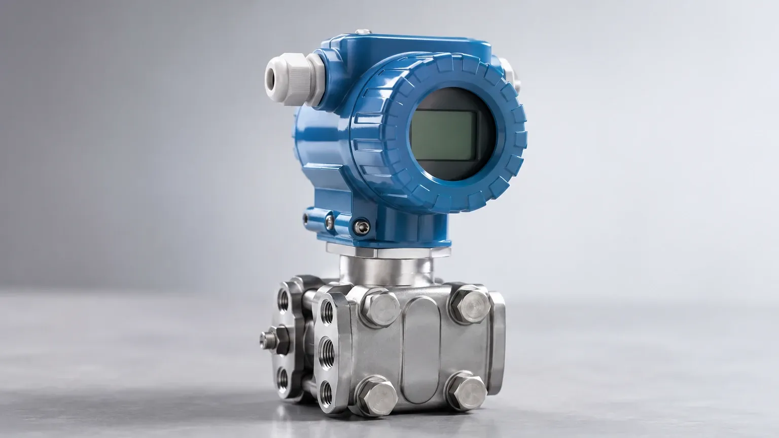
In the landscape of industrial automation and process control, the digital differential pressure sensor has emerged as a cornerstone technology for monitoring fluid levels, flow rates, and filter conditions. Unlike traditional analog transmitters, digital versions integrate advanced microprocessors to provide higher accuracy, long-term stability, and multi-variable data transmission. For engineers and facility managers in sectors such as water treatment, chemical processing, and oil and gas, understanding the mechanics and selection criteria of these instruments is essential for maintaining operational efficiency and safety.
Measurement Principles of Differential Pressure
The fundamental principle behind a digital differential pressure sensor is the measurement of the difference between two pressure points. In industrial applications, this is typically represented as the High-Pressure (HP) side and the Low-Pressure (LP) side. The sensor calculates the delta (ΔP) between these two points, which can then be mathematically converted into level, flow, or density measurements.
Hydrostatic Level Measurement
For liquid level applications, particularly in pressurized vessels, the sensor measures the hydrostatic head. The pressure exerted by a liquid column is proportional to its height and density, following the formula:
P = ρ × g × h
Where:
* P is the hydrostatic pressure.
* ρ (rho) is the density of the liquid (kg/m³).
* g is the acceleration due to gravity (approximately 9.81 m/s²).
* h is the height of the liquid (m).
In an enclosed tank, the pressure above the liquid (ullage pressure) must be subtracted to find the true liquid level. A digital differential pressure sensor accomplishes this by connecting the LP side to the top of the vessel and the HP side to the bottom. The digital processor then subtracts the top pressure from the total bottom pressure, leaving only the pressure exerted by the liquid column.
Flow Rate Calculation
When used with a primary flow element like an orifice plate or Venturi tube, the sensor measures the pressure drop across the restriction. According to Bernoulli’s principle, the square root of the differential pressure is proportional to the flow rate. Digital sensors are particularly valued here because they can perform the square root extraction internally, providing a direct linear output of the flow velocity.
The Evolution to Digital Technology
Traditional analog sensors transmit a simple 4-20mA signal. While reliable, they are limited in the amount of information they can convey. A modern digital differential pressure sensor, such as those manufactured by Welk, utilizes digital signal processing (DSP) to enhance performance in several ways:
1. Linearization: Digital sensors can correct for non-linearities in the sensing element, ensuring higher accuracy across the entire measurement range.
2. Temperature Compensation: Built-in temperature sensors allow the device to adjust the pressure reading in real-time, mitigating errors caused by thermal expansion or contraction of the fill fluid.
3. Communication Protocols: These devices often support HART, Modbus, or PROFIBUS protocols. This allows for remote configuration, diagnostics, and the transmission of secondary variables (like process temperature) over the same two wires used for power.
4. High Turn-down Ratios: Digital electronics allow for a much wider "turn-down" or rangeability. A single sensor can often be calibrated to measure a small fraction of its maximum range without a significant loss in accuracy.
Key Evaluation Criteria for Industrial Applications
Selecting the correct digital differential pressure sensor requires a thorough analysis of the process environment. Engineers should evaluate the following factors to ensure long-term reliability.
Accuracy and Total Probable Error (TPE)
While many manufacturers cite "reference accuracy" (often as low as ±0.075%), the Total Probable Error is a more realistic metric for B2B procurement. TPE accounts for the effects of static pressure, ambient temperature variations, and long-term drift. For critical chemical processes, a sensor with low TPE is vital for maintaining mass balance.
Static Pressure Limits
In many high-pressure oil and gas applications, the differential pressure might be small (e.g., 50 kPa), but the static line pressure could be as high as 20 MPa (200 bar). The sensor must be able to withstand these high static pressures on both sides of the diaphragm without shifting the zero point or sustaining mechanical damage.
Material Compatibility
The wetted parts of the sensor—specifically the diaphragms and process flanges—must be compatible with the process media. While 316L stainless steel is standard, aggressive chemicals may require Tantalum, Monel, or Hastelloy C-276. For more specialized requirements, you can Review product options and application support to match materials to specific chemical profiles.
Selection Guide and Comparison Table
To assist in the initial stages of project planning, the following table compares common configurations for digital differential pressure sensors based on application type.
| Application Type | Recommended Diaphragm Material | Typical Output | Key Feature Required |
| :— | :— | :— | :— |
| Water Treatment | 316L Stainless Steel | 4-20mA + HART | IP68 ingress protection |
| Corrosive Chemical | Hastelloy C or Tantalum | Modbus RTU | Remote seals for isolation |
| Oil & Gas (Upstream) | Monel or Inconel | HART / Foundation Fieldbus | High static pressure rating |
| Food & Beverage | 316L (Electropolished) | 4-20mA | Sanitary (Tri-clamp) fittings |
| Steam Flow | 316L Stainless Steel | 4-20mA + HART | High-temperature impulse lines |
Installation Considerations and Best Practices
The accuracy of a digital differential pressure sensor is often more dependent on the installation than the instrument itself. Proper piping and mounting are critical.
Impulse Line Configuration
Impulse lines (the small-bore pipes connecting the process to the sensor) must be installed to prevent gas or liquid traps:
* For Gas Measurement: The sensor should be mounted above the process tapping points so that any condensed liquid drains back into the process line.
* For Liquid Measurement: The sensor should be mounted below the tapping points so that any gas bubbles can rise back into the process line.
* Slope: Impulse lines should have a minimum slope of 1:12 (approx. 8%) to facilitate the movement of trapped air or condensate.
Use of Manifolds
A 3-valve or 5-valve manifold is essential for every digital differential pressure sensor installation. These manifolds allow the sensor to be isolated from the process for maintenance and enable the "zeroing" of the sensor under actual static line pressure conditions. This ensures that the ΔP reading starts from a true zero, even when the system is pressurized.
Environmental Protection
In outdoor or harsh industrial environments, sensors should be equipped with sunshades or heated enclosures if the process fluid is prone to freezing or if the electronics are subject to extreme thermal cycling. Welk industrial level measurement instruments are designed with robust housings, but site-specific protection extends the service life of the sensitive digital components.
Limitations and Common Risks
Despite their advanced capabilities, digital differential pressure sensors are not universal solutions. Users must be aware of specific limitations:
1. Diaphragm Fatigue: In applications with rapid pressure pulsations (such as near positive displacement pumps), the sensing diaphragm can suffer from mechanical fatigue over time.
2. Hydrogen Permeation: In high-pressure hydrogen service, hydrogen atoms can diffuse through standard metal diaphragms, eventually forming bubbles in the fill fluid and causing significant measurement drift. Gold-plated diaphragms are often required in these instances.
3. Clogging: If the process fluid contains high solids or is prone to crystallization, the narrow impulse lines or the small cavities in front of the sensor diaphragm can clog. In these cases, a "Remote Seal" or "Diaphragm Seal" system is preferred, which uses a large-area flexible diaphragm to transmit pressure via a capillary tube filled with silicone oil.
4. Signal Interference: While digital signals are more robust than analog ones, poor shielding or improper grounding in environments with heavy VFD (Variable Frequency Drive) usage can still introduce noise into the digital communication bus.
Frequently Asked Questions (FAQs)
Q: How often should a digital differential pressure sensor be calibrated?
A: Most modern digital sensors offer excellent long-term stability (e.g., ±0.1% of URL per 5-10 years). However, in regulated industries or critical safety loops, an annual calibration check is recommended. Many digital sensors allow for a "smart" calibration where only the zero and span are adjusted digitally without needing to manipulate physical components.
Q: Can a differential pressure sensor be used for density measurement?
A: Yes. By fixing the distance between two pressure taps (h) and measuring the differential pressure (P), the density (ρ) can be calculated using the formula ρ = P / (g × h). This is common in chemical blending tanks.
Q: What is the difference between a "wet" and "dry" leg in level measurement?
A: In level measurement for tanks with condensable vapors (like steam), the LP impulse line may fill with liquid. This is a "wet leg." The weight of this liquid must be accounted for in the sensor's calibration. If the vapor does not condense, the line remains filled with gas, known as a "dry leg."
Q: Does the orientation of the sensor matter?
A: Yes. Most sensors are calibrated in a specific orientation (usually vertical). Mounting the sensor in a different orientation can cause a zero-shift due to the weight of the internal fill fluid acting on the diaphragm. This can usually be corrected by performing a zero-trim after installation.
Conclusion
The transition to digital differential pressure sensors has provided industrial operators with unprecedented levels of data and accuracy. By integrating these sensors into a broader automation strategy, facilities can reduce maintenance costs through remote diagnostics and improve process yields through tighter control. When selecting a sensor, it is imperative to look beyond the base price and consider the long-term implications of material compatibility, static pressure requirements, and installation geometry. For those seeking reliable, accurate, and cost-effective level measurement solutions, exploring the technical specifications of professional manufacturers like Welk is the recommended next step. For further technical details and product ranges, visit the Main Page to access comprehensive engineering resources.


