Differenzdrucksensor
Differenzdrucksensor
In the landscape of industrial process automation, the differenzdrucksensor (differential pressure sensor) serves as a cornerstone technology for level, flow, and pressure monitoring. While modern non-contacting methods like radar have gained significant market share, differential pressure (DP) remains a preferred solution for many high-pressure, high-temperature, and vacuum applications. This guide provides a technical overview of how a differenzdrucksensor functions in level measurement, the criteria for selection, and the practical considerations necessary for successful field integration.
Measurement Principles of the Differenzdrucksensor
The fundamental principle behind using a differenzdrucksensor for level measurement is hydrostatic pressure. According to Pascal’s Law, the pressure exerted by a static liquid column is directly proportional to its height and the density of the fluid. The mathematical relationship is expressed as:
P = ρ × g × h
Where:
* P is the hydrostatic pressure (measured in Pascals or bar).
* ρ (rho) is the density of the liquid (kg/m³).
* g is the gravitational acceleration (approximately 9.81 m/s²).
* h is the height of the liquid column (meters).
Open vs. Closed Vessels
In an open vessel (vented to the atmosphere), the differenzdrucksensor measures the pressure at the bottom of the tank relative to the ambient atmospheric pressure. The "high-pressure" side of the sensor is connected to the process at the lowest measurement point, while the "low-pressure" side is vented to the air.
In a closed or pressurized vessel, the measurement becomes more complex. The sensor must account for the internal tank pressure (static pressure) acting on the surface of the liquid. To do this, the differenzdrucksensor is connected to both the bottom of the tank (high-pressure side) and the top of the tank (low-pressure side). By subtracting the head pressure from the total pressure at the bottom, the sensor isolates the hydrostatic pressure generated solely by the liquid height.
Technical Components and System Architecture
A complete DP level measurement system often involves more than just the sensor itself. Depending on the process media and environment, several auxiliary components are utilized:
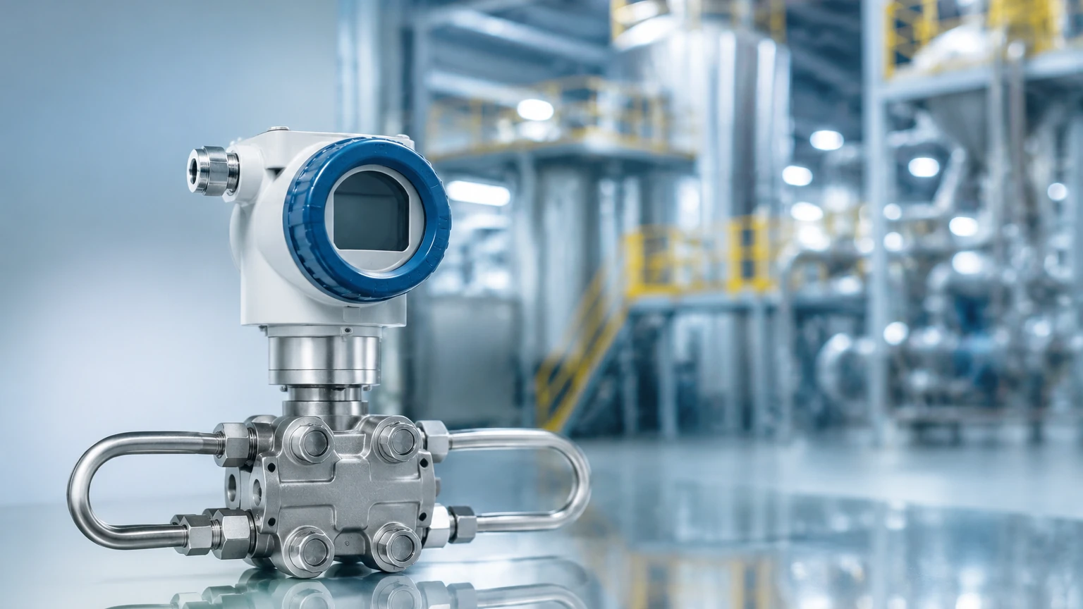
1. The Transmitter: This is the core differenzdrucksensor unit that converts the physical pressure difference into an electrical signal, typically 4-20mA with HART, Profibus, or Foundation Fieldbus protocols.
2. Impulse Lines: These are small-bore pipes that transmit the process pressure from the vessel taps to the sensor. They are common in clean, non-viscous applications.
3. Remote Seals (Chemical Seals): For corrosive, highly viscous, or hygienic applications, remote seals are used. These consist of a flexible diaphragm connected to the sensor via a capillary tube filled with a transmission fluid (e.g., silicone oil). This prevents the process media from entering the sensor body.
4. Manifolds: A three-valve or five-valve manifold is usually installed between the process and the sensor. These allow for the isolation of the sensor for maintenance, zero-point calibration, and equalization of pressure to prevent over-ranging during startup.
Selection Criteria for Industrial Applications
Choosing the correct differenzdrucksensor requires a thorough analysis of the process conditions. Engineers should evaluate the following parameters before procurement:
Pressure and Temperature Limits
Every sensor has a Maximum Working Pressure (MWP). It is vital to ensure the sensor can withstand the static pressure of the vessel, which may be significantly higher than the differential pressure being measured. Furthermore, process temperatures exceeding 100°C often necessitate the use of remote seals or cooling elements to protect the transmitter electronics.
Diaphragm Material Compatibility
The wetted parts, specifically the sensing diaphragm, must be chemically compatible with the process fluid. While 316L stainless steel is standard, aggressive media like hydrochloric acid or seawater may require exotic materials such as Hastelloy C, Tantalum, or Monel. For more information on material options and specific instrument configurations, you can visit the Main Page of professional manufacturers.
Accuracy and Turndown Ratio
Industrial-grade sensors typically offer accuracies ranging from 0.075% to 0.04% of the calibrated span. The "turndown ratio" refers to the range over which the sensor can be adjusted without significant loss of accuracy. High turndown ratios (e.g., 100:1) allow a single sensor model to be used across various tank heights in a facility.
Practical Selection Table
The following table compares the differenzdrucksensor with other common level measurement technologies found in industrial automation.
| Feature | Differenzdrucksensor | Radar (GWR/Non-Contact) | Ultrasonic Sensor |
| :— | :— | :— | :— |
| Measurement Type | Contacting (Pressure-based) | Non-contacting (Time-of-Flight) | Non-contacting (Sound-based) |
| Accuracy | High (0.05% – 0.1%) | Very High (±1mm to ±3mm) | Medium (0.25%) |
| Effect of Foam | Minimal | Significant (for non-contact) | High |
| Effect of Density | High (Requires constant ρ) | None | None |
| Max Temperature | Very High (with seals) | Up to 450°C | Generally < 80°C |
| Maintenance | Medium (Impulse line cleaning) | Low | Low |
| Vessel Type | Best for pressurized tanks | Best for solids/liquids | Best for open sumps |
Installation Considerations and Best Practices
Proper installation is the most critical factor in the long-term reliability of a differenzdrucksensor. Incorrect mounting can lead to "gas pockets" in liquid lines or "liquid traps" in gas lines, both of which introduce significant measurement errors.
Orientation of Impulse Lines
* Liquid Service: The sensor should ideally be mounted below the process taps. This ensures that the impulse lines remain filled with liquid and that any gas bubbles can migrate back into the vessel.
* Gas Service: The sensor should be mounted above the process taps. This allows any condensate to drain back into the vessel, preventing liquid from blocking the pressure signal.
Wet Leg vs. Dry Leg
In closed tanks with condensable vapors, the low-pressure impulse line can fill with liquid over time.
* Dry Leg: Used when the vapor does not condense at ambient temperatures. The line remains filled with gas.
* Wet Leg: The low-pressure line is intentionally filled with a reference liquid (usually the process fluid or a stable oil). This creates a constant head pressure on the low side, which is then mathematically compensated for in the transmitter's calibration.
Capillary Systems
If using remote seals with capillaries, it is essential to mount the sensor such that the capillary lengths are equal on both the high and low sides. This helps to cancel out the effects of ambient temperature fluctuations, which cause the fill fluid inside the capillaries to expand or contract.
Limitations and Risks
Despite its versatility, the differenzdrucksensor has inherent limitations that must be managed:
1. Density Sensitivity: Since the sensor measures pressure, any change in the liquid's density (caused by temperature changes or concentration shifts) will be interpreted as a change in level. In processes with fluctuating temperatures, a temperature-compensated density calculation is required.
2. Clogging and Plugging: Impulse lines are susceptible to clogging if the process media contains solids or if the fluid crystallizes at ambient temperatures. Regular flushing or the use of diaphragm seals is necessary in these cases.
3. Static Pressure Effects: Very high static pressures can cause a "zero shift" in the sensor. While modern digital sensors compensate for this internally, it remains a factor during the initial commissioning and zero-calibration phase.
Frequently Asked Questions (FAQ)
Q: Can a differenzdrucksensor be used for interface measurement?
A: Yes. By measuring the pressure difference between two points in a vessel containing two immiscible liquids (like oil and water), the sensor can determine the height of the interface, provided the densities of both liquids remain relatively constant.
Q: How often should a differenzdrucksensor be calibrated?
A: Calibration intervals depend on the criticality of the process and the stability of the sensor. In most industrial environments, a bench check every 12 to 24 months is standard, though many modern smart transmitters can go longer without significant drift.
Q: What happens if the low-pressure side of a closed tank sensor is vented to the atmosphere by mistake?
A: The sensor will measure the sum of the liquid's hydrostatic pressure and the tank's internal head pressure. This will result in a significantly higher (and incorrect) level reading, which could lead to an overfill situation.
Q: Are there hygienic versions of these sensors?
A: Yes. For the food, beverage, and pharmaceutical industries, differenzdrucksensors are available with flush-mounted diaphragms and hygienic process connections (like Tri-Clamp) that eliminate dead spaces where bacteria could grow.
Conclusion
The differenzdrucksensor remains a fundamental tool for industrial level measurement due to its robustness and ability to handle extreme process conditions. By understanding the relationship between pressure and height, and by carefully selecting materials and installation configurations, engineers can achieve highly accurate and repeatable results. For those looking to explore specific product options, including radar and ultrasonic alternatives, reviewing technical specifications on the Main Page of an established manufacturer is the recommended next step in the project planning process.