Digital Gas Flow Meters
Digital Gas Flow Meters
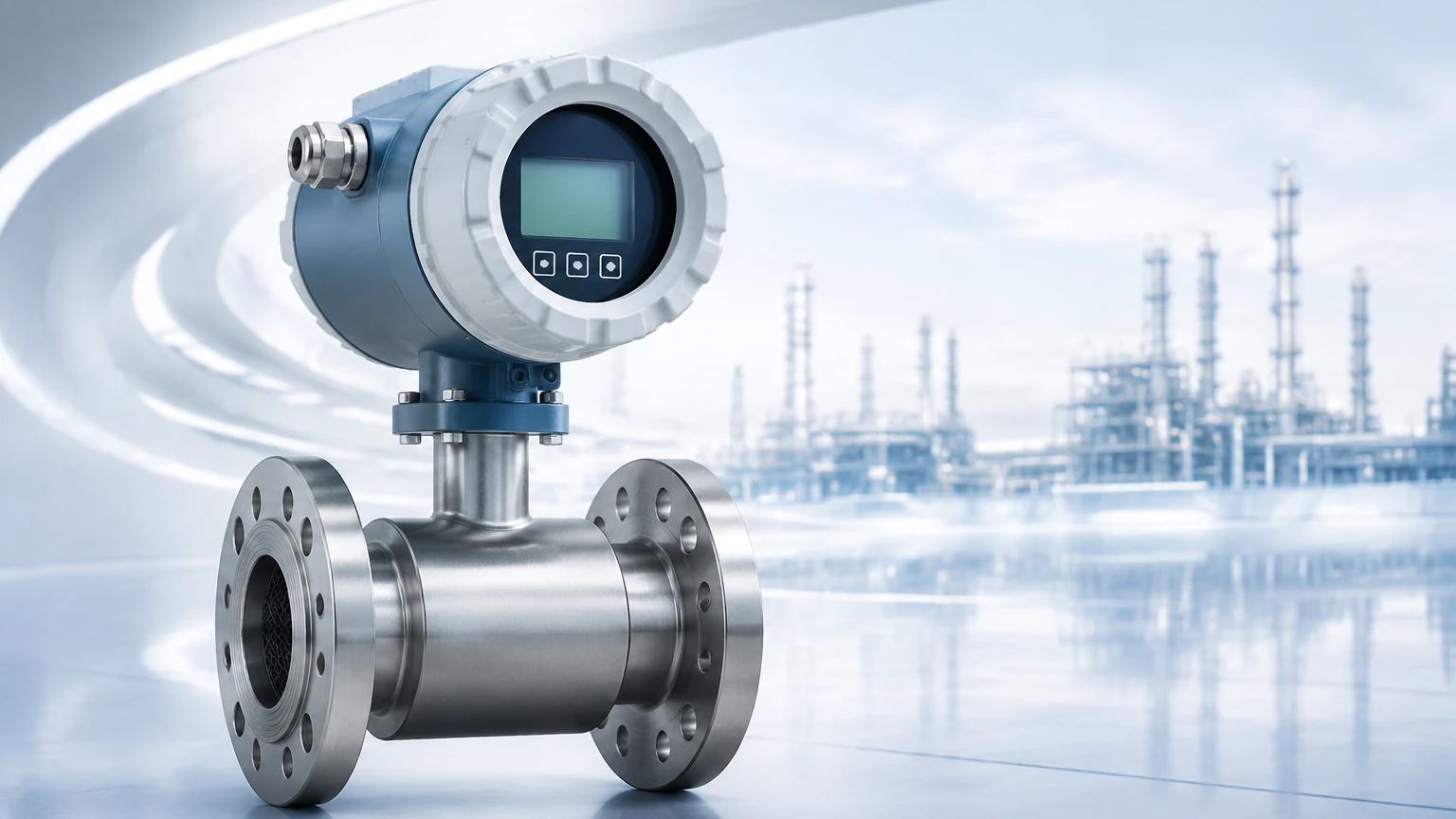
In modern industrial processing, the transition from mechanical to digital gas flow meters represents a significant leap in operational efficiency and data accuracy. Digital gas flow meters are specialized instruments designed to measure the volume or mass flow rate of gases—such as compressed air, natural gas, nitrogen, and oxygen—and convert these measurements into digital signals for monitoring and control. Unlike traditional analog gauges, these devices provide high-resolution data, local digital displays, and integration capabilities with PLC, DCS, and SCADA systems.
For process engineers and plant managers, selecting the right digital gas flow meter requires a deep understanding of the underlying measurement physics, the specific properties of the gas being measured, and the environmental conditions of the installation site. This guide explores the core technologies, selection criteria, and practical installation strategies for industrial gas flow measurement.
Understanding Measurement Principles for Gas Flow
Gas measurement is inherently more complex than liquid measurement due to the compressibility of gases. Changes in pressure and temperature significantly alter the density and volume of a gas. Consequently, digital gas flow meters utilize several distinct physical principles to ensure accuracy.
Thermal Dispersion (Mass Flow)
Thermal mass flow meters operate on the principle of thermal dispersion. The sensor typically consists of two RTDs (Resistance Temperature Detectors); one is a reference sensor that measures the gas temperature, and the other is a heated sensor. As gas flows past the heated sensor, it carries away heat. The meter measures the electrical power required to maintain a constant temperature differential between the two sensors. Since this heat transfer is directly proportional to the number of gas molecules (the mass) passing by, the device provides a direct mass flow reading without requiring separate pressure or temperature compensation.
Vortex Shedding (Volumetric Flow)
Vortex meters utilize the Von Kármán effect. When gas flows past a "shedder bar" placed in the stream, vortices (swirls) are created on alternating sides. The frequency of these vortices is directly proportional to the velocity of the gas. Digital vortex meters use piezoelectric sensors to detect these pressure pulses. While primarily volumetric, many modern digital versions include integrated temperature and pressure sensors to calculate compensated mass flow.
Ultrasonic Transit-Time
Ultrasonic digital gas flow meters use pairs of transducers to send and receive ultrasonic pulses through the gas stream. Pulses traveling with the flow move faster than those traveling against it. The difference in transit time is used to calculate the flow velocity. This technology is non-intrusive and offers extremely high accuracy, making it a preferred choice for custody transfer and high-volume industrial applications.
Differential Pressure (DP)
Digital DP meters measure the pressure drop across a primary element, such as an orifice plate or a Venturi tube. A digital pressure transmitter then calculates the flow rate based on Bernoulli’s equation. While a traditional method, the "digital" aspect comes from high-precision multivariable transmitters that perform real-time calculations for density and flow rate.
Key Evaluation Criteria for Industrial Digital Gas Flow Meters
Selecting a meter involves more than just matching pipe sizes. Engineering teams must evaluate the following technical parameters to ensure long-term reliability.
1. Turndown Ratio: This is the ratio between the maximum and minimum flow rates the meter can accurately measure. For example, a meter with a 100:1 turndown ratio can measure a maximum of 1000 m³/h and a minimum of 10 m³/h. Thermal mass meters typically offer the highest turndown ratios, which is critical for detecting leaks during low-demand periods.
2. Gas Composition: The physical properties of the gas (density, viscosity, and thermal conductivity) affect the meter's performance. For corrosive gases like Hydrogen Sulfide (H2S), sensors must be constructed from specialized alloys like Hastelloy. For explosive environments, the meter must carry ATEX or IECEx certifications.
3. Accuracy and Repeatability: In B2B industrial contexts, accuracy is usually expressed as a percentage of the reading or a percentage of the full scale. Repeatability is equally important for process consistency, ensuring the meter provides the same output for the same flow conditions over time.
4. Pressure Drop: Some meters, like DP or vortex meters, introduce an obstruction in the pipe that causes a permanent loss of pressure. In low-pressure systems, this can be a significant drawback. Ultrasonic and thermal meters generally offer much lower pressure drops.
Selection Table: Comparing Gas Flow Technologies
The following table provides a high-level comparison of common digital gas flow meter technologies used in industrial automation.
| Technology | Typical Accuracy | Turndown Ratio | Pressure Drop | Primary Advantage |
| :— | :— | :— | :— | :— |
| Thermal Mass | ±1% of Reading | 100:1 | Very Low | Direct mass flow; no P/T compensation needed. |
| Vortex | ±1% of Rate | 20:1 | Medium | No moving parts; excellent for high-velocity gas. |
| Ultrasonic | ±0.5% to ±1% | 50:1 | Negligible | Non-intrusive; very high precision. |
| Digital DP | ±0.5% to ±2% | 10:1 | High | Well-understood; easy to calibrate in the field. |
| Coriolis | ±0.5% of Rate | 100:1 | High | Highest precision; measures mass, density, and temp. |
Installation Guidelines and Best Practices
Even the most advanced digital gas flow meter will fail to provide accurate data if installed incorrectly. The following engineering considerations are mandatory for successful deployment:
* Straight Pipe Runs: Most flow technologies require a specific length of straight pipe upstream and downstream of the meter to ensure a fully developed, non-turbulent flow profile. Typically, a minimum of 10 to 20 pipe diameters (D) upstream and 5D downstream is recommended. If space is limited, flow conditioners (vanes or perforated plates) may be required.
* Orientation: While many digital meters can be installed in any orientation, horizontal installation is generally preferred for gases. If installed vertically, the flow should ideally be upward to prevent the accumulation of any potential liquids (condensate) on the sensor.
* Moisture and Particulates: Digital gas flow meters, especially thermal and vortex types, are sensitive to moisture droplets and dust. Filters and moisture traps should be installed upstream if the gas is not "instrument-grade" dry. Moisture can cause thermal meters to over-read significantly because water carries away heat more effectively than gas.
* Communication Protocols: Ensure the meter’s digital output matches the facility’s infrastructure. Common options include 4-20mA with HART, Modbus RTU (RS485), and Foundation Fieldbus. Digital communication allows for remote diagnostics and configuration, reducing the need for physical access to the meter in hazardous areas.
Common Risks and Operational Limitations
Engineers must be aware of the potential failure modes and limitations of digital gas flow meters to prevent process downtime.
* Calibration Drift: Over time, sensors may accumulate coatings or experience electronic drift. Regular verification against a master meter or factory recalibration is necessary, especially in regulated industries like oil and gas.
* Non-Ideal Gas Behavior: At very high pressures, gases do not behave according to the ideal gas law. Digital meters must be programmed with the correct compressibility factors (Z-factors) for the specific gas and operating pressure.
* Vibration and Noise: Vortex meters are particularly sensitive to pipe vibration. If the installation site is near a large compressor or pump, the mechanical noise may interfere with the sensor’s ability to detect vortices, leading to erratic readings.
Integrating Flow and Level Measurement Systems
In many industrial applications, gas flow measurement is used in conjunction with level measurement to provide a complete mass balance of a system. For example, in pressurized chemical storage tanks, monitoring the gas blanket flow can indicate a breach or a malfunction in the pressure control system. Similarly, in wastewater treatment, measuring the biogas flow from an anaerobic digester is essential for energy management, while hydrostatic or radar level sensors monitor the sludge levels.
For engineers looking to integrate these flow readings with high-precision tank inventory systems, exploring the Main Page provides access to a full suite of level measurement technologies that complement digital gas flow monitoring. Combining accurate flow data with reliable level instrumentation ensures that automated systems can respond to real-time changes in process volume and pressure.
Frequently Asked Questions (FAQ)
Q: Can digital gas flow meters measure steam?
A: Yes, but not all types. Vortex meters are the industry standard for steam measurement because they can handle high temperatures and the physical nature of saturated or superheated steam. Thermal mass meters are generally not suitable for steam due to the high moisture content.
Q: What is the difference between Actual Cubic Meters (ACm) and Normal Cubic Meters (Nm³)?
A: Actual Cubic Meters (ACm) refers to the volume of gas at the current operating pressure and temperature. Normal Cubic Meters (Nm³) refers to the volume the gas would occupy at standard reference conditions (typically 0°C and 1.01325 bar). Digital meters often convert ACm to Nm³ automatically using integrated temperature and pressure sensors.
Q: Do digital gas flow meters require a power supply?
A: Yes, most industrial digital meters require a 24V DC or 110/220V AC power supply. Some low-power models are loop-powered (2-wire), drawing power from the 4-20mA signal line, but these may have limited display brightness or fewer communication options.
Q: How often should a digital gas flow meter be recalibrated?
A: Most manufacturers recommend recalibration every 1 to 3 years, depending on the criticality of the application and the cleanliness of the gas. Meters used for custody transfer or environmental compliance may have stricter, legally mandated calibration intervals.
By adhering to these technical guidelines and carefully matching the meter technology to the specific gas properties, B2B procurement and engineering teams can ensure accurate, reliable, and maintenance-friendly gas flow measurement within their facilities.