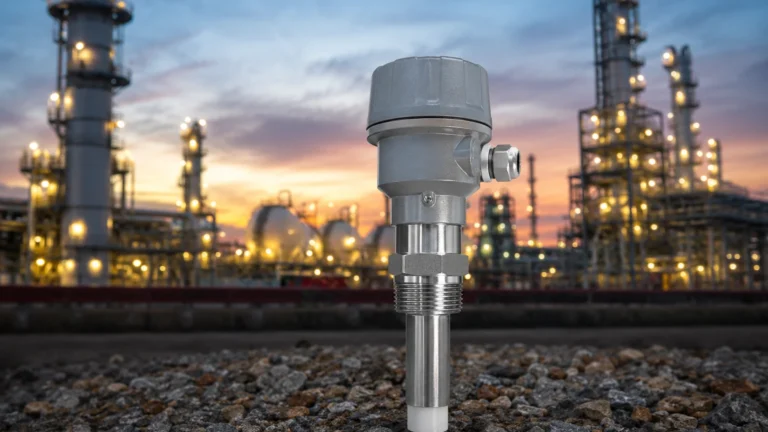
Doppler Flow Sensor
Doppler Flow Sensor
In the landscape of industrial process control, the ability to measure the movement of fluids without breaching the integrity of the piping system is a significant operational advantage. The Doppler flow sensor represents a specialized category of ultrasonic flow measurement technology designed specifically for liquids containing suspended solids or entrained gases. While often discussed alongside radar and ultrasonic level meters, Doppler flow sensors address the kinetic aspect of fluid management, providing real-time velocity data essential for mass balance, pump control, and efficiency monitoring.
For engineers and plant managers seeking reliable instrumentation, understanding the specific environmental requirements for these sensors is critical. As a professional manufacturer, Welk provides a comprehensive range of measurement solutions, which can be further explored on our Main Page, where technical specifications for various industrial sensors are detailed.
Measurement Principles of Doppler Technology
The Doppler flow sensor operates on the principle of the Doppler Effect, a physical phenomenon first described by Christian Doppler in 1842. This principle states that the frequency of a wave changes relative to an observer if the source of the wave is moving. In the context of industrial flow measurement, the sensor acts as both the source and the observer.
The Ultrasonic Signal Path
An ultrasonic transducer is mounted on the exterior of a pipe. It transmits a continuous high-frequency sound wave—typically between 640 kHz and 2 MHz—through the pipe wall and into the flowing liquid. For the measurement to be successful, the liquid must contain "acoustic reflectors." These are usually suspended solids, sediment, or small air bubbles.
As the ultrasonic wave hits these moving particles, the signal is reflected back toward a second transducer (or a receiving element in a dual-function probe). Because the particles are moving with the fluid, the frequency of the reflected signal is shifted.
The Mathematical Foundation
The relationship between the frequency shift and the fluid velocity is expressed by the following simplified formula:
Δf = 2 · f0 · (v/c) · cos(θ)
Where:
* Δf: The Doppler frequency shift.
* f0: The transmitted frequency.
* v: The velocity of the fluid (and the particles within it).
* c: The speed of sound in the fluid.
* θ: The angle of the ultrasonic beam relative to the flow direction.
By measuring the difference between the transmitted and received frequencies, the sensor's electronics can calculate the velocity of the fluid. When combined with the known cross-sectional area of the pipe, the volumetric flow rate (m³/h or liters/second) is determined.
Doppler vs. Transit-Time: Choosing the Right Ultrasonic Method
It is a common point of confusion in industrial procurement to conflate Doppler sensors with Transit-Time ultrasonic flow meters. While both use ultrasound and are often "clamp-on" devices, they are intended for opposite fluid conditions.
| Feature | Doppler Flow Sensor | Transit-Time Flow Meter |
| :— | :— | :— |
| Fluid Requirement | Dirty liquids (solids/bubbles required) | Clean liquids (no solids/bubbles) |
| Mechanism | Frequency shift from reflection | Time-of-flight difference between pulses |
| Minimum Solids | Typically >100 ppm of 100-micron particles | Typically <1% total suspended solids |
| Common Use | Sludge, wastewater, pulp, mining slurries | Potable water, oils, deionized chemicals |
| Installation | Single or dual-head clamp-on | Two transducers (upstream/downstream) |
Practical Selection Criteria
Selecting a Doppler flow sensor requires a detailed analysis of the process media and the physical piping environment. Unlike hydrostatic level transmitters or magnetic level gauges, the performance of a Doppler sensor is highly dependent on the "acoustic transparency" of the pipe and the "reflectivity" of the fluid.
Fluid Characteristics
The primary requirement is the presence of reflectors. If the liquid is too clean (e.g., distilled water), there will be no reflected signal, and the sensor will fail to provide a reading. Conversely, if the concentration of solids is too high (e.g., thick sludge exceeding 30% concentration), the ultrasonic signal may be completely attenuated before it can return to the receiver.
Pipe Material and Condition
Doppler sensors work best with sonically conductive materials such as carbon steel, stainless steel, copper, and most plastics (PVC, PE). However, pipes with internal liners—especially those made of materials like cement, rubber, or glass—can pose challenges. If there is an air gap between the liner and the pipe wall, the ultrasonic signal will be blocked entirely.
Velocity Range
Most industrial Doppler sensors are calibrated for velocities ranging from 0.1 m/s to 10 m/s (0.3 to 30 ft/s). It is important to ensure that the expected flow rate falls within this window, particularly at the lower end where the signal-to-noise ratio can decrease.
Technical Selection Table
Use the following table as a baseline for determining if a Doppler flow sensor is appropriate for your application.
| Parameter | Requirement/Range | Notes |
| :— | :— | :— |
| Suspended Solids | > 100 ppm (parts per million) | Particles should be > 100 microns |
| Gas Bubbles | > 75 ppm | Small, entrained air/gas bubbles |
| Pipe Sizes | 12.5 mm to 4500 mm | Clamp-on sensors are versatile for large pipes |
| Velocity | 0.05 m/s to 12 m/s | Accuracy typically ±2% of full scale |
| Pipe Wall Thickness | Up to 25 mm | Depends on material and sensor frequency |
| Fluid Temperature | -40°C to +150°C | High-temp transducers available for specialized use |
Installation Considerations and Best Practices
Proper installation is the single most influential factor in the accuracy of a Doppler flow sensor. Because the sensor measures the velocity of particles, it must be placed in a location where the flow profile is fully developed and stable.
1. Straight Pipe Requirements
To avoid turbulence, which causes erratic readings, the sensor should be installed on a straight section of pipe. The general rule of thumb is:
* Upstream: At least 10 pipe diameters (10D) of straight pipe after any elbows, valves, or pumps.
* Downstream: At least 5 pipe diameters (5D) of straight pipe before the next fitting.
2. Transducer Positioning
On horizontal pipes, avoid mounting the sensor at the very top or the very bottom. The top of the pipe may contain air pockets, while the bottom may have settled sediment. The ideal mounting position is at the "3 o'clock" or "9 o'clock" positions (the sides of the pipe).
3. Surface Preparation and Coupling
Since the ultrasonic signal must pass through the pipe wall, the contact surface must be smooth. For metal pipes, this often involves sanding or grinding away rust and paint. A coupling agent (ultrasonic grease or gel) is applied between the sensor face and the pipe to eliminate any air gaps. For permanent installations, silicone-based adhesives or epoxy may be used.
4. Full Pipe Requirement
The pipe must be completely full of liquid. If the pipe is only partially full, the sensor will not be able to calculate an accurate volumetric flow because the cross-sectional area of the liquid is unknown. In such cases, integrating the flow sensor with an ultrasonic level sensor to measure liquid depth is a common engineering workaround.
Limitations and Potential Risks
While highly effective for difficult fluids, Doppler flow sensors have inherent limitations that engineers must account for during the design phase:
* Signal Attenuation: In very large pipes or highly viscous fluids, the ultrasonic signal may lose energy before returning to the sensor, leading to a "signal loss" error.
* Velocity Profile Sensitivity: Doppler sensors tend to measure the velocity of the particles closest to the pipe wall rather than the average velocity of the entire stream. Modern digital signal processing (DSP) helps compensate for this, but it remains a factor in absolute accuracy.
* Wall Buildup: If the interior of the pipe develops a thick layer of scale or biofilm, the signal may be reflected off the stationary scale rather than the moving fluid, resulting in a zero-flow reading even when liquid is moving.
* Interference: High-frequency noise from nearby VFDs (Variable Frequency Drives) or heavy machinery can occasionally interfere with the sensor electronics if shielded cabling is not used.
Frequently Asked Questions (FAQ)
Q: Can a Doppler flow sensor measure the flow of clean water?
A: Generally, no. Without suspended solids or air bubbles to reflect the signal, the sensor will not receive a return frequency. For clean water, a Transit-Time ultrasonic meter is the correct choice.
Q: Does the pipe material affect the measurement?
A: Yes. Materials that absorb sound, such as certain rubbers or loosely bonded liners, can prevent the sensor from working. Most rigid metals and plastics work well.
Q: How often does the sensor need to be calibrated?
A: Because the sensor has no moving parts and does not contact the fluid, it does not suffer from mechanical wear. Recalibration is typically only necessary if the pipe dimensions change or if the fluid composition shifts significantly.
Q: Can it be used on vertical pipes?
A: Yes, provided the flow is moving upward. This ensures the pipe remains full. Downward flow in vertical pipes often results in partial filling or cavitation, which will cause inaccurate readings.
Q: Is it possible to measure flow through a concrete pipe?
A: It is very difficult. Concrete is porous and contains air voids that scatter ultrasonic waves. For concrete piping, an insertion-style electromagnetic flow meter or a specialized transit-time meter is usually preferred.
Conclusion
The Doppler flow sensor is an indispensable tool for monitoring "challenging" fluids in industries ranging from wastewater treatment to mining. By leveraging the frequency shift of ultrasonic waves, these sensors provide a non-invasive, low-maintenance solution for measuring the velocity of slurries and aerated liquids. For organizations looking to integrate these sensors into a broader automation strategy—including radar level meters or chemical dosing systems—selecting the right technology based on fluid reflectivity and pipe conductivity is paramount.
For further technical guidance on selecting the appropriate instrument for your specific industrial application, please refer to the resources available on our Main Page.