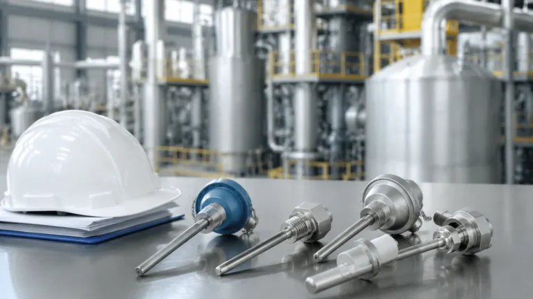
Intrinsically Safe Sensor
Intrinsically Safe Sensor
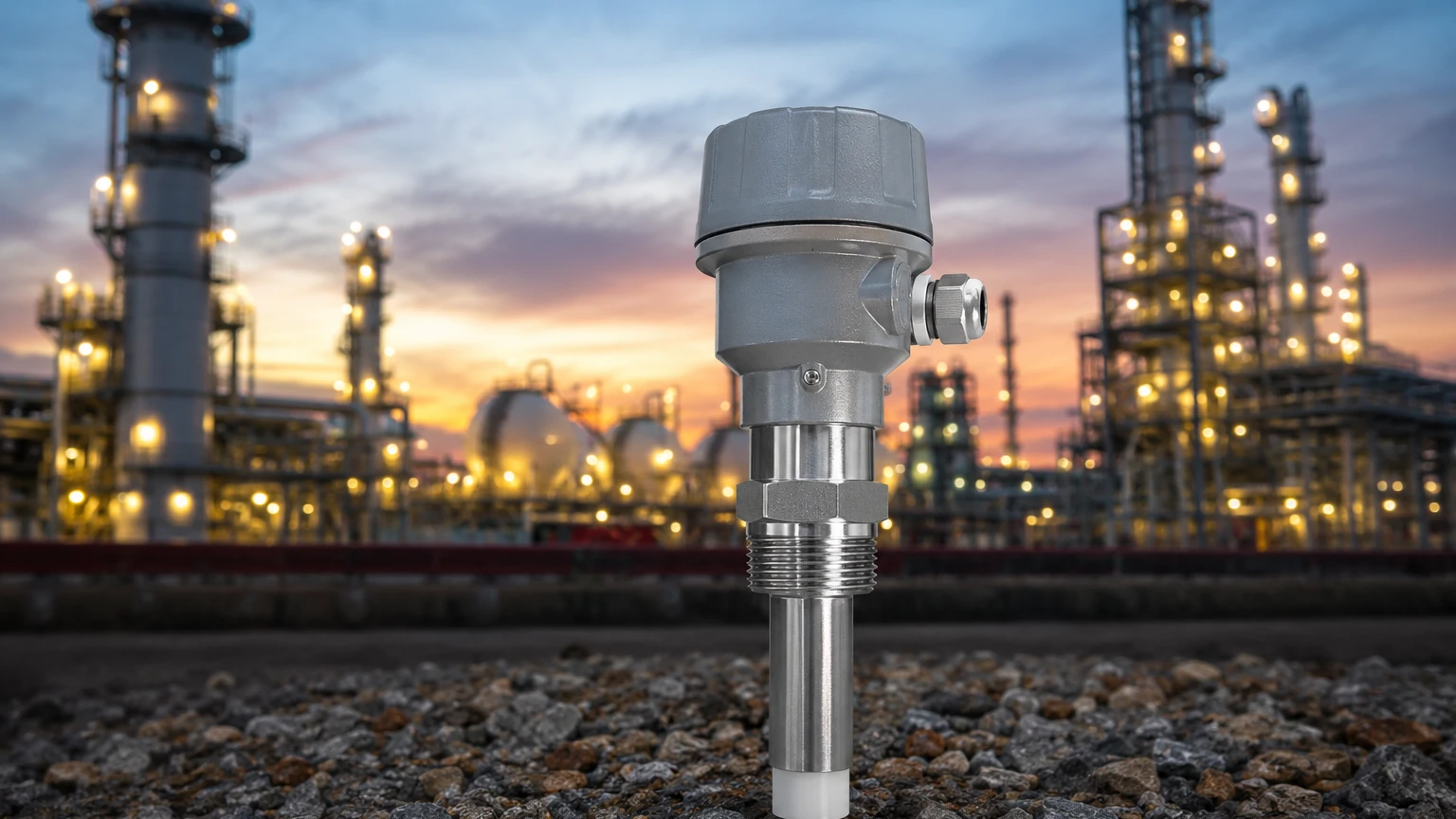
In industrial environments where flammable gases, vapors, or combustible dusts are present, the selection of instrumentation is a critical safety decision. An intrinsically safe sensor represents a specific approach to explosion protection, focusing on the limitation of electrical and thermal energy within a circuit to levels that are insufficient to cause ignition. Unlike other protection methods that rely on containing an explosion, intrinsic safety (IS) ensures that a spark or heat cannot occur in the first place, even under fault conditions.
For process engineers and plant managers, understanding the implementation of an intrinsically safe sensor is essential for compliance with international standards such as ATEX and IECEx. This guide examines the principles, selection criteria, and installation requirements for these specialized instruments in level measurement applications.
The Principle of Intrinsic Safety in Level Measurement
The fundamental principle of intrinsic safety is the limitation of energy. In a hazardous area, three elements are required for an explosion: a fuel (gas or dust), an oxidizer (oxygen in the air), and an ignition source (heat or a spark). While the first two are often inherent to the process, the ignition source must be controlled.
An intrinsically safe sensor is designed to operate with very low power. The protection is achieved through two primary mechanisms:
1. Electrical Energy Limitation: The voltage ($U_i$) and current ($I_i$) entering the hazardous area are restricted so that no spark can generate enough energy to ignite the specific atmosphere.
2. Thermal Energy Limitation: The surface temperature of components is kept below the auto-ignition temperature of the surrounding gas or dust, even if a component fails.
To achieve this, the sensor must be part of an "intrinsically safe system." This system typically includes the sensor (the simple or certified apparatus) located in the hazardous area, the interconnecting cable, and an associated apparatus (such as a Zener barrier or galvanic isolator) located in the safe area. The barrier acts as a gatekeeper, ensuring that even if a high-voltage surge occurs in the control room, the energy reaching the sensor remains within safe limits.
Types of Intrinsically Safe Sensors for Level Detection
Welk manufactures a variety of level measurement instruments designed for hazardous locations. Depending on the media and the specific zone classification, different technologies may be employed.
Radar Level Meters
Radar sensors, particularly Frequency Modulated Continuous Wave (FMCW) radar, are frequently used in tanks containing volatile organic compounds (VOCs) or fuels. Because they are non-contact, they are ideal for corrosive or agitated liquids. Intrinsically safe radar units are engineered to operate at low power consumption while maintaining high-frequency precision.
Ultrasonic Level Sensors
Ultrasonic sensors use sound waves to measure distance. In hazardous chemical storage, these sensors provide a cost-effective solution for atmospheric tanks. IS-rated ultrasonic sensors are often used in wastewater sumps where methane gas may be present.
Hydrostatic Level Transmitters
For deep wells or pressurized vessels, hydrostatic transmitters measure the pressure exerted by the liquid column. These sensors are often submerged, requiring robust sealing and IS certification to ensure the electrical signals traveling through the cable do not pose a risk in the event of cable damage.
Magnetic Level Gauges and Switches
Magnetic gauges use a float with an internal magnet. When paired with an intrinsically safe reed switch or transmitter, they provide a highly reliable, power-efficient method for monitoring levels in high-pressure or high-temperature hazardous environments.
Key Evaluation Criteria for Hazardous Areas
When selecting an intrinsically safe sensor, it is not enough to simply look for an "IS" label. The device must be matched to the specific hazards of the site. This involves evaluating three primary classifications:
1. Zone Classification
* Zone 0 / 20: Areas where an explosive atmosphere is present continuously or for long periods. Sensors here must meet the highest safety standards (typically Ex ia).
* Zone 1 / 21: Areas where an explosive atmosphere is likely to occur in normal operation. (Typically Ex ib).
* Zone 2 / 22: Areas where an explosive atmosphere is not likely to occur in normal operation, and if it does, it will only exist for a short time. (Typically Ex ic).
2. Gas and Dust Groups
Different substances require different amounts of energy to ignite. For example, Hydrogen (Group IIC) is much easier to ignite than Propane (Group IIA). An intrinsically safe sensor certified for Group IIC is safe for use in IIA and IIB environments, but the reverse is not true.
3. Temperature Class (T-Rating)
The T-rating indicates the maximum surface temperature the sensor will reach. This must be lower than the auto-ignition temperature of the gases present. Ratings range from T1 (450°C / 842°F) to T6 (85°C / 185°F).
Selection Table: IS Level Sensor Comparison
| Sensor Technology | Typical Zone Suitability | Best For | Advantages | Limitations |
| :— | :— | :— | :— | :— |
| 80GHz Radar | Zone 0, 1, 2 | Volatile chemicals, fuels | High accuracy, non-contact | Higher initial cost |
| Ultrasonic | Zone 1, 2 | Water treatment, acids | Cost-effective, no moving parts | Affected by foam and vacuum |
| Hydrostatic | Zone 0, 1, 2 | Submerged tanks, wells | Easy installation | Media density must be known |
| Level Switch | Zone 0, 1, 2 | Overfill protection | Simple, high reliability | Point measurement only |
Installation and Wiring Considerations
The integrity of an intrinsically safe sensor installation depends heavily on the wiring and the associated apparatus. Failure to follow these guidelines can negate the safety benefits of the IS design.
Entity Parameters
To ensure a safe system, the "Entity Parameters" of the sensor must be matched with the barrier. These include:
* $U_i$ (Max Input Voltage): Must be $\ge U_o$ (Max Output Voltage of the barrier).
* $I_i$ (Max Input Current): Must be $\ge I_o$ (Max Output Current of the barrier).
* $P_i$ (Max Input Power): Must be $\ge P_o$ (Max Output Power of the barrier).
* $C_i$ and $L_i$ (Internal Capacitance/Inductance): When added to the cable capacitance/inductance, the total must be $\le C_o$ and $L_o$ of the barrier.
Cable Requirements
Cables used for intrinsically safe circuits must be clearly identified, usually with a light blue jacket. They should be physically separated from non-IS cables by a minimum distance (typically 50 mm / 2 inches) or by a grounded metal partition to prevent electromagnetic induction from high-voltage lines, which could induce dangerous energy levels into the IS circuit.
Grounding and Bonding
Proper grounding is vital, especially when using Zener barriers, which divert fault currents to the ground. A high-integrity earth connection (usually less than 1 Ohm) is required to ensure the barrier functions correctly during a fault.
Limitations and Common Risks
While an intrinsically safe sensor is the preferred choice for many hazardous applications, it does have limitations:
* Power Constraints: Because the energy is strictly limited, IS sensors may have lower signal strength or slower update rates compared to explosion-proof (Ex d) versions. This can be a factor in long-range radar applications or when driving heavy-duty displays.
* System Complexity: An IS installation requires more components (barriers/isolators) and stricter documentation than a standard installation.
* Maintenance Errors: The most common risk is the "unauthorized modification." Replacing an IS-rated sensor with a standard version or bypassing a barrier during troubleshooting creates a significant explosion hazard.
Frequently Asked Questions (FAQs)
Q: Can I use an intrinsically safe sensor without a barrier?
A: No. A certified intrinsically safe sensor only provides safety when connected to a compatible associated apparatus (barrier or isolator) that limits the energy entering the hazardous area.
Q: What is the difference between Ex ia and Ex ib?
A: Ex ia is the most stringent, requiring the device to remain safe even after two independent faults. It is suitable for Zone 0. Ex ib requires safety after one fault and is suitable for Zone 1.
Q: How do I identify an IS sensor in the field?
A: Look for the specific marking on the nameplate (e.g., Ex ia IIC T6 Ga) and the presence of blue-jacketed cabling or specific IS labeling on the terminal housing.
Conclusion
Implementing an intrinsically safe sensor is a proactive step toward ensuring plant safety and regulatory compliance in hazardous environments. By limiting energy at the source, these sensors provide a robust layer of protection that is inherently fail-safe. When selecting a device, engineers must carefully consider the zone classification, gas groups, and temperature ratings to ensure the instrument is fit for purpose.
Welk offers a comprehensive range of level measurement solutions tailored for these demanding conditions. For technical support in selecting the right instrument for your hazardous area application, you can Review product options and application support on our Main Page. Ensuring the correct match between sensor technology and safety certification is the first step toward a reliable and secure industrial operation.