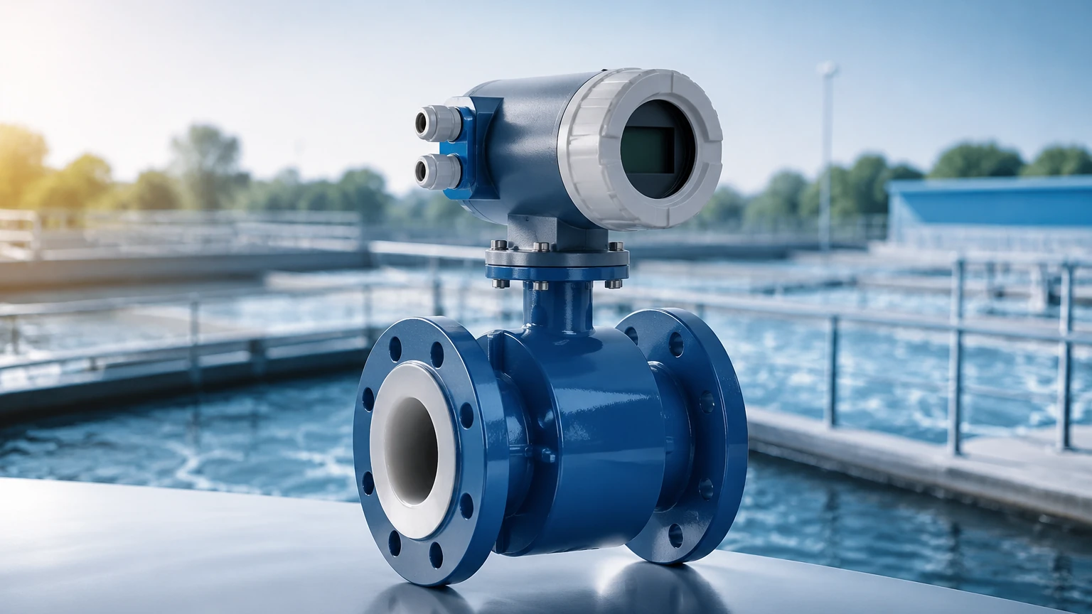
Dura Mag Flow Meter
Dura Mag Flow Meter
In the realm of industrial fluid management and agricultural irrigation, the transition from mechanical measurement to electronic sensing has significantly improved operational efficiency. The dura mag flow meter represents a specialized category of electromagnetic flow meters (mag meters) designed to address the challenges of harsh environments, conductive fluids, and remote installations where traditional power infrastructure may be lacking. Unlike mechanical turbine or propeller meters, these devices utilize electromagnetic induction to provide high-accuracy readings without the maintenance overhead of moving parts.
For engineers and facility managers, selecting a flow meter requires a deep understanding of the underlying physics, the specific design advantages of the instrument, and how it integrates into a broader process control system. This guide explores the technical foundations of the dura mag flow meter, its practical applications, and the critical selection criteria for industrial implementation.
The Physics of Electromagnetic Flow Measurement
To understand the performance of a dura mag flow meter, one must first examine the principle of Faraday’s Law of Electromagnetic Induction. This law states that a conductor moving through a magnetic field produces an electrical voltage proportional to the velocity of that conductor. In the context of a flow meter, the "conductor" is the liquid itself.
The Mathematical Foundation
The relationship is expressed by the formula:
E = k × B × D × v
Where:
* E is the induced voltage generated by the fluid.
* k is a constant specific to the instrument.
* B is the strength of the magnetic field generated by the internal coils.
* D is the distance between the electrodes (typically the pipe diameter).
* v is the average velocity of the fluid.
As the fluid flows through the pipe (the magnetic field), the electrodes positioned on the pipe walls pick up the induced voltage. Because the magnetic field strength and the pipe diameter are constant, the voltage is directly proportional to the fluid velocity. This allows the meter to calculate the volumetric flow rate with high precision, provided the fluid meets a minimum threshold of electrical conductivity, usually around 20 μS/cm.
Technical Characteristics of the Dura Mag Flow Meter
The dura mag flow meter is specifically engineered to overcome the common failure points of standard mag meters, such as liner delamination and electrode fouling. Its design philosophy centers on longevity and field-serviceability.
Fusion-Bonded Epoxy Design
One of the most distinctive features of this meter is the use of fusion-bonded epoxy. In many industrial mag meters, a separate plastic or rubber liner (such as PTFE or EPDM) is inserted into the metal flow tube. Under conditions of high pressure, vacuum, or extreme temperature cycling, these liners can collapse or tear. The dura mag utilizes a fusion-bonded epoxy coating that is applied directly to the interior of the tube, creating a seamless, durable surface that eliminates the risk of liner failure. This is particularly beneficial in agricultural and wastewater applications where debris or abrasive particles may be present.
Power and Connectivity
Designed for versatility, these meters often feature internal battery power, making them ideal for remote sites. A typical internal battery can last up to five years, depending on the sampling rate. For integrated industrial systems, they also support external power (DC or AC) and provide standard outputs such as 4-20mA, pulse, and Modbus. This flexibility ensures that flow data can be transmitted to a central SCADA system or a local PLC for real-time monitoring.
Selection Criteria and Sizing
Choosing the correct size for a dura mag flow meter is critical. Unlike mechanical meters, which are often sized based on the pipe diameter, electromagnetic meters should be sized based on the expected flow velocity to ensure the best signal-to-noise ratio.
Practical Selection Table
| Pipe Size (mm) | Pipe Size (inches) | Min Flow Rate (m³/h) | Max Flow Rate (m³/h) | Typical Accuracy | Pressure Rating (bar) |
| :— | :— | :— | :— | :— | :— |
| 50 mm | 2" | 1.5 | 50 | ±0.5% | 10.3 |
| 100 mm | 4" | 6.0 | 200 | ±0.5% | 10.3 |
| 150 mm | 6" | 14.0 | 450 | ±0.5% | 10.3 |
| 200 mm | 8" | 25.0 | 800 | ±0.5% | 10.3 |
| 300 mm | 12" | 55.0 | 1800 | ±0.5% | 10.3 |
*Note: Flow rates are approximate and vary based on specific model calibrations. For precise sizing, engineers should consult the Main Page of the manufacturer's technical documentation to review product options and application support.*
Velocity Considerations
For optimal performance, the fluid velocity should ideally fall between 0.5 m/s and 5.0 m/s (approx. 1.6 ft/s to 16.4 ft/s). If the flow velocity is too low, the induced voltage may be too small to distinguish from electrical noise. If the velocity is too high, it can lead to increased pressure drop and potential erosion of the epoxy coating over long periods.
Installation Guidelines for Optimal Accuracy
While the dura mag flow meter is known for its tolerance of non-ideal piping configurations, certain installation standards must be followed to maintain the specified accuracy of ±0.5% of flow.
Straight Pipe Requirements
Turbulence caused by elbows, valves, or pumps can distort the flow profile, leading to measurement errors. The general industry standard is to have at least 5 diameters (5D) of straight pipe upstream and 2 diameters (2D) downstream from the meter. However, some advanced mag meters are calibrated to handle "zero-straight-run" conditions (U0/D0), though providing some straight run is always preferred for stability.
Mounting Orientation
* Horizontal Installation: The meter should be installed in a low point of the piping system to ensure the pipe is always full. The electrodes should be positioned at the 3 o'clock and 9 o'clock positions to prevent air bubbles (at the top) or sediment (at the bottom) from interfering with the signal.
* Vertical Installation: Flow should always move upward. This ensures the pipe remains full and prevents the formation of air pockets.
Grounding and Shielding
Since the meter measures millivolts of induced electricity, it is highly sensitive to stray electrical currents in the fluid or the piping. In plastic or lined piping systems, grounding rings are essential to provide a common electrical reference between the fluid and the meter's electronics. Failure to ground the meter properly is the most common cause of erratic readings.
Performance Limitations and Environmental Constraints
Despite its robustness, the dura mag flow meter is not a universal solution for every application. Understanding its limitations is key to avoiding project failures.
1. Conductivity Requirements: It cannot measure non-conductive fluids such as oils, fuels, or deionized water. If the fluid conductivity drops below the minimum threshold, the meter will fail to produce a signal.
2. Fluid Temperature: While the epoxy coating is durable, it has temperature limits. Typically, these meters are rated for fluids between 0°C and 60°C (32°F to 140°F). Applications involving steam or high-temperature chemical processing may require specialized ceramic-lined meters.
3. Entrained Air: Large bubbles or foam in the liquid will be measured as fluid volume, leading to over-registration of flow. If the pipe is only partially full, the meter cannot provide an accurate reading.
4. Vacuum Conditions: Although the fusion-bonded epoxy is superior to loose liners, extreme vacuum conditions can still cause stress on the coating. It is important to verify the vacuum rating if the application involves suction-side installation.
Maintenance and Troubleshooting FAQ
Q: How often does the meter need recalibration?
A: Because there are no moving parts to wear out, the meter's geometry remains constant. Most industrial users perform a verification check every 1–2 years using a portable ultrasonic meter or a master meter to ensure the electronics are still within spec.
Q: What causes a "Signal Loss" error?
A: This is usually caused by an empty pipe, extremely low conductivity, or a coating of non-conductive material (like grease or oil) over the electrodes. Cleaning the electrodes or ensuring a full pipe usually resolves this.
Q: Can the meter be submerged?
A: Many dura mag models are rated IP68, meaning they can withstand temporary or continuous submersion. However, the cable glands and junction box must be properly sealed according to the manufacturer's instructions.
Q: How does the meter handle solids?
A: The meter can handle a significant percentage of suspended solids (slurries). However, if the solids are magnetic (like iron filings), they will interfere with the magnetic field and cause significant errors.
Conclusion and System Integration
The dura mag flow meter is a high-performance instrument that bridges the gap between simple mechanical measurement and complex process automation. Its lack of moving parts and resistance to liner failure make it a cost-effective choice for long-term installations in water treatment, irrigation, and general industrial water monitoring.
In many modern facilities, flow measurement is only one part of the equation. To achieve full process visibility, flow data must be paired with accurate level measurement in storage tanks and reservoirs. For instance, comparing the flow rate into a tank with the change in level measured by an ultrasonic or radar sensor allows for sophisticated leak detection and inventory reconciliation. Engineers looking to optimize their entire liquid handling system should visit the Main Page to explore how advanced level transmitters and flow meters work in tandem to provide a comprehensive view of industrial operations.