E&h Level Sensor
E&h Level Sensor
In the landscape of industrial process automation, the accuracy of level measurement is a critical factor for operational safety, inventory management, and process efficiency. Among the various solutions available to engineers, the e&h level sensor—referring to the instruments developed by Endress+Hauser—represents a global benchmark for precision and reliability. However, selecting the right technology for a specific application requires a deep understanding of measurement principles, environmental variables, and the specific constraints of the medium being measured.
This guide provides a technical overview of the primary level measurement technologies used in modern industry, comparing high-end solutions with practical alternatives to help procurement and engineering teams make informed decisions. For those seeking detailed specifications on a broad range of industrial instruments, you can review product options and application support on the Main Page of the Welk technical catalog.
Understanding Industrial Level Measurement Principles
Before selecting a specific sensor model, it is essential to understand the physics behind the measurement. Industrial level sensors generally fall into two categories: continuous level measurement and point level detection.
Time-of-Flight (ToF) Principle
Most non-contact sensors, including radar and ultrasonic types, operate on the Time-of-Flight principle. The sensor emits a signal (electromagnetic or acoustic) that travels to the surface of the medium, reflects, and returns to the receiver. The distance ($D$) is calculated using the formula:
$$D = \frac{c \cdot t}{2}$$
Where $c$ is the speed of the wave in the medium (usually air) and $t$ is the measured time delay. In radar applications, $c$ is the speed of light, while in ultrasonic applications, it is the speed of sound.
Guided Wave Radar (GWR)
Guided Wave Radar uses the TDR (Time Domain Reflectometry) principle. High-frequency microwave pulses are guided along a probe (rod or cable). When the pulse hits the surface of the medium, the change in the dielectric constant ($ε_r$) causes a reflection. This method is highly effective for liquids with low dielectric constants and is less affected by foam or turbulence than non-contact radar.
Hydrostatic Pressure
Hydrostatic sensors measure the pressure exerted by a liquid column. The pressure ($P$) at the bottom of a tank is proportional to the height ($h$) of the liquid, its density ($ρ$), and gravity ($g$):
$$P = \rho \cdot g \cdot h$$
This is a reliable method for vented tanks where the density remains constant.
Selection Criteria for e&h level sensor and Industrial Alternatives
Choosing between an e&h level sensor and other industrial-grade alternatives like those provided by Welk depends on several technical parameters. The following table outlines the primary selection criteria for common technologies.
| Technology | Typical Range | Accuracy | Medium Compatibility | Temperature/Pressure Limits |
| :— | :— | :— | :— | :— |
| 80GHz Radar | Up to 125m | ±1mm | Liquids, Solids, Corrosives | -196°C to +450°C / 160 bar |
| Ultrasonic | Up to 15m | ±2mm | Water, Wastewater, Chemicals | -40°C to +80°C / 3 bar |
| Guided Wave Radar | Up to 45m | ±2mm | Liquids, Interface, Powders | -50°C to +200°C / 40 bar |
| Hydrostatic | Up to 200m | ±0.1% FS | Clean liquids, Slurries | -10°C to +100°C / High static pressure |
Dielectric Constant (ε_r) Considerations
For radar-based measurement, the dielectric constant of the material is the most important factor. Materials with a high $ε_r$ (e.g., water, $ε_r ≈ 80$) reflect signals strongly. Hydrocarbons and oils have low $ε_r$ values (often < 2.0), which may require high-sensitivity radar or Guided Wave Radar to ensure a reliable signal-to-noise ratio.
Key Technologies and Their Application Boundaries
1. Radar Level Measurement (80 GHz vs. 26 GHz)
Modern radar sensors have shifted toward the 80 GHz frequency band. The shorter wavelength allows for a narrower beam angle (as small as 3°), which minimizes interference from internal tank structures like agitators, heating coils, or ladders. While a premium e&h level sensor in the Micropilot series often utilizes this high-frequency technology, Welk offers comparable 80 GHz radar solutions designed for aggressive chemical environments and high-temperature storage tanks.
* Advantages: Non-contact, maintenance-free, unaffected by vacuum or high pressure.
* Limitations: Performance can be degraded by extremely heavy foam or very low dielectric materials in non-contact modes.
2. Ultrasonic Level Sensors
Ultrasonic sensors are the cost-effective standard for water and wastewater applications. They are ideal for open channels, sumps, and atmospheric tanks.
* Advantages: Economical, easy to install, no moving parts.
* Limitations: Sensitive to temperature fluctuations (which change the speed of sound), heavy dust, steam, and surface foam which can absorb the acoustic signal.
3. Hydrostatic Level Transmitters
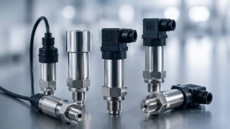
For deep wells or pressurized vessels where top-mounting is not feasible, hydrostatic transmitters are the preferred choice. These sensors are often submersible or mounted via a flange at the tank bottom.
* Advantages: Simple principle, excellent for deep-water measurement.
* Limitations: Requires accurate knowledge of the liquid's density. If the density changes due to temperature or concentration shifts, the level reading will drift unless compensated.
Installation Best Practices and Engineering Considerations
Proper installation is as critical as sensor selection. Even a high-precision e&h level sensor will fail to provide accurate data if environmental factors are ignored.
Blocking Distance (Dead Zone)
All Time-of-Flight sensors have a "blocking distance" or "dead zone" directly beneath the sensor face. No measurement can occur within this zone (typically 100mm to 500mm). Engineers must ensure the maximum fill level of the tank does not enter this zone to avoid signal loss.
Nozzle Geometry
When mounting radar or ultrasonic sensors on nozzles, the nozzle height and diameter must be considered. If a nozzle is too narrow or too long, the signal may reflect off the nozzle walls before reaching the medium. For 80 GHz radar, nozzle interference is significantly reduced, but it remains a primary concern for 26 GHz and ultrasonic units.
Avoiding Obstacles
The sensor should be positioned so that the signal beam does not intersect with internal tank components. If an agitator is present, the sensor can often be programmed to "mask" the recurring reflection from the blades using a false signal suppression algorithm.
Environmental Protection
In outdoor installations, sunshields should be used to prevent internal electronics from overheating. For hydrostatic sensors in open water, lightning protection and desiccant cartridges (for vented cables) are necessary to prevent moisture ingress into the reference tube.
Maintenance, Troubleshooting, and Lifecycle Management
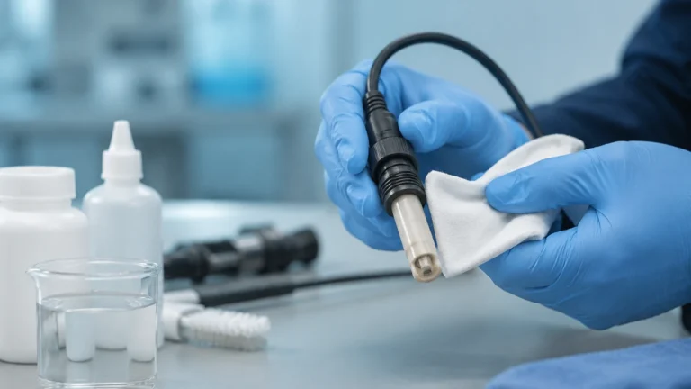
While modern solid-state level sensors are largely maintenance-free, periodic verification is required in regulated industries (e.g., pharmaceutical or food production).
1. Build-up and Scaling: In applications involving lime milk or wastewater, material can build up on the sensor face. While many radar sensors can "see through" thin layers of build-up, heavy scaling will eventually attenuate the signal.
2. Signal Loss (Echo Loss): This is often caused by heavy foam or a turbulent surface. Increasing the damping or switching to a Guided Wave Radar probe can resolve these issues.
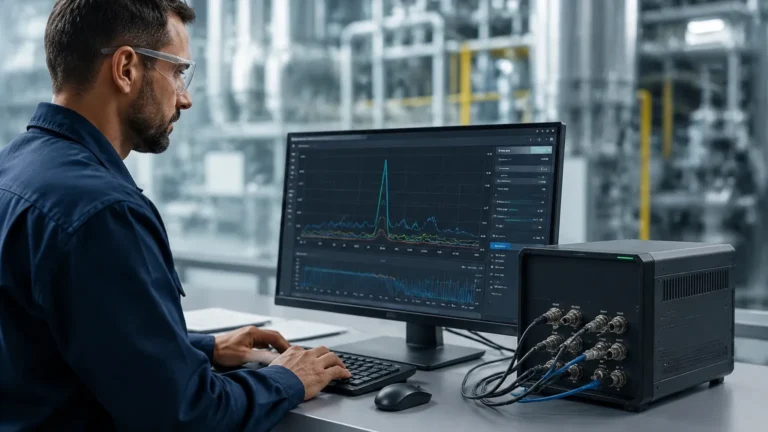
3. Communication Protocols: Most industrial level sensors support 4-20mA HART, Modbus RTU, or Profibus. Ensure the sensor’s integration with the PLC/SCADA system allows for remote diagnostics, which can significantly reduce downtime during troubleshooting.
Frequently Asked Questions (FAQ)
Q: Can I use a radar sensor to measure the level of a solid, such as grain or plastic pellets?
A: Yes, but it is recommended to use an 80 GHz radar or a specifically designed solids radar. Solids often have an angle of repose that can deflect signals away from the receiver, and dust can interfere with lower-frequency sensors.
Q: How does foam affect an e&h level sensor compared to an ultrasonic sensor?
A: Ultrasonic sensors are highly sensitive to foam because the air bubbles absorb the sound waves. Radar is generally more robust, though dense, thick foam can still cause signal attenuation. In cases of extreme foam, Guided Wave Radar is the most reliable choice.
Q: Is it necessary to recalibrate a hydrostatic sensor if the liquid temperature changes?
A: If the temperature change significantly alters the density of the liquid, then yes, the level calculation will be affected. High-end systems often include a temperature sensor to provide real-time density compensation.
Q: What is the benefit of using a 2-wire vs. a 4-wire sensor?
A: 2-wire sensors are powered by the current loop (4-20mA), which simplifies wiring and reduces costs. 4-wire sensors have a separate power supply and are typically used for high-power applications, such as heated sensors or units with intensive processing requirements.
For engineers looking to optimize their process control with reliable level measurement technology, understanding these technical boundaries is the first step. To explore specific models and technical documentation, visit the Main Page for a comprehensive range of industrial measurement solutions.