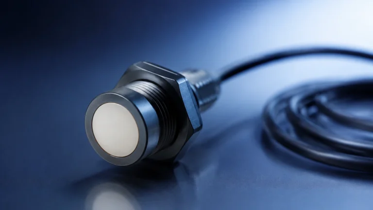
Vortex Flow Meter
Vortex Flow Meter
In the landscape of industrial process control, the accurate measurement of fluid flow is as critical as level monitoring. The vortex flow meter has established itself as a versatile, reliable, and highly accurate instrument for measuring the flow rate of liquids, gases, and steam. Based on the principle of vortex shedding, these meters are particularly valued in industries such as power generation, chemical processing, and water treatment due to their lack of moving parts and wide rangeability.
Understanding the mechanics, application limits, and installation requirements of a vortex flow meter is essential for engineers and plant managers seeking to optimize their process efficiency. This guide provides a comprehensive technical overview of vortex flow measurement technology to assist in informed procurement and system design.
Principles of Operation: The Von Kármán Effect
The fundamental principle behind a vortex flow meter is the Von Kármán effect. When a fluid—whether liquid, gas, or steam—passes an unstreamlined object (referred to as a bluff body or shedder bar), it cannot follow the contours of the object on both sides simultaneously. This results in the fluid separating from the surface of the object and forming alternating swirls or "vortices" in its wake.
The Frequency-Velocity Relationship
The frequency at which these vortices are shed is directly proportional to the velocity of the fluid. This relationship is defined by the Strouhal number ($St$), a dimensionless parameter that remains constant over a wide range of Reynolds numbers. The formula governing this measurement is:
$$f = St \times \frac{v}{d}$$
Where:
* $f$ is the frequency of vortex shedding.
* $St$ is the Strouhal number (specific to the bluff body shape).
* $v$ is the flow velocity.
* $d$ is the width of the bluff body.
Because the width of the shedder bar and the Strouhal number are fixed by the meter’s design, the electronics within the meter can calculate the flow velocity by simply counting the number of vortices generated over a specific period. By multiplying this velocity by the cross-sectional area of the pipe, the meter determines the volumetric flow rate.
Detection Methods
To count the vortices, manufacturers typically embed sensors within or behind the shedder bar. The most common detection method involves piezoelectric crystals that sense the pressure fluctuations caused by each vortex. Other methods include ultrasonic sensors that detect the shift in a beam as it passes through the vortex trail or thermal sensors that detect the cooling effect of the swirling fluid.
Technical Construction and Components
A standard vortex flow meter consists of three primary components: the meter body, the shedder bar, and the transmitter (electronics).
1. Meter Body: Usually constructed from stainless steel (316 or 304) or carbon steel, the body is designed to withstand high pressures and temperatures. It is available in wafer-style, flanged, or insertion configurations.
2. Shedder Bar: This is the heart of the meter. Its geometry is precision-engineered to ensure stable vortex shedding across a broad range of flow rates. It must be robust enough to withstand the mechanical stress of fluid impact.
3. Transmitter: The transmitter converts the mechanical or pressure signals from the sensor into an electrical output, such as a 4-20mA signal, pulse output, or digital protocols like HART, Modbus, or Foundation Fieldbus.
For complex applications, multi-variable vortex flow meters are often employed. These units include integral temperature and pressure sensors, allowing the meter to calculate mass flow—a feature particularly useful for steam and compressed air applications where density varies with environmental conditions.
Media Compatibility: Steam, Gas, and Liquids
The versatility of the vortex flow meter is one of its greatest strengths. However, the physical properties of the media dictate the meter's performance.
Steam Measurement
One of the most common uses for vortex technology is steam flow measurement. Unlike many other flow technologies, vortex meters can handle the high temperatures and velocities associated with saturated and superheated steam. They provide excellent long-term stability and are less prone to wear than turbine meters in these harsh environments.
Gas and Compressed Air
Vortex meters are highly effective for measuring dry gases and compressed air. They offer a low pressure drop compared to orifice plates, which translates to energy savings in large-scale pneumatic systems. It is important to ensure the gas is clean; excessive moisture or particulate matter can interfere with vortex formation or damage the sensor.
Liquid Applications
For low-viscosity liquids, such as water or light chemicals, vortex meters provide high accuracy (typically ±0.75% to ±1.0% of rate). However, they are not suitable for highly viscous fluids (e.g., heavy oils) because high viscosity dampens the formation of vortices, causing the meter to stop reading at low flow velocities.
Selection Criteria and Engineering Specifications
When selecting a vortex flow meter, engineers must evaluate several parameters to ensure the device operates within its linear range. The following table provides a general comparison of typical specifications found in industrial-grade vortex meters.
| Parameter | Typical Specification (Metric) | Typical Specification (Imperial) |
| :— | :— | :— |
| Pipe Sizes | DN15 to DN300 (Flanged) | 1/2" to 12" (Flanged) |
| Temperature Range | -200°C to +400°C | -328°F to +752°F |
| Pressure Rating | Up to 100 bar (standard) | Up to 1450 psi |
| Accuracy (Liquid) | ±0.75% of rate | ±0.75% of rate |
| Accuracy (Gas/Steam) | ±1.0% to ±1.5% of rate | ±1.0% to ±1.5% of rate |
| Turndown Ratio | 10:1 to 30:1 | 10:1 to 30:1 |
| Reynolds Number Req. | > 20,000 | > 20,000 |
For comprehensive instrumentation solutions, including level and flow monitoring, visit the Main Page of our primary resource site to review product options and application support.
Critical Installation Requirements
The accuracy of a vortex flow meter is heavily dependent on the flow profile of the fluid as it enters the meter. Turbulence or non-uniform flow profiles can lead to significant measurement errors.
Straight Pipe Runs
To ensure a fully developed flow profile, vortex meters require specific lengths of straight pipe upstream and downstream of the installation point.
* Upstream: Typically 10 to 20 pipe diameters (D) depending on the upstream obstruction (e.g., a single elbow requires 10D, while two elbows in different planes may require 30D).
* Downstream: Typically 5 pipe diameters (D) to prevent back-pressure fluctuations from affecting the shedder bar.
If these distances cannot be met, flow straighteners or conditioners must be installed to eliminate swirl and turbulence.
Orientation and Piping
* Horizontal Piping: The meter can be installed in any orientation, but for liquid applications, the pipe must remain full at all times. For steam applications, the sensor should ideally be mounted to the side or bottom to prevent heat damage to the electronics from rising heat.
* Vertical Piping: Flow should always be upward for liquid applications to ensure the pipe is full and to prevent air pockets from forming around the shedder bar.
* Vibration: Vortex meters are sensitive to pipe vibration, as the sensor may misinterpret vibration as vortex shedding. Installations should be located away from pumps or heavy machinery, or the pipe should be securely braced on either side of the meter.

Operational Limitations and Environmental Factors
While robust, the vortex flow meter is not a "one-size-fits-all" solution. Several factors can limit its effectiveness:
1. Low Flow Cut-off: Below a certain velocity, the fluid does not have enough kinetic energy to form detectable vortices. This is defined by the minimum Reynolds number. If the flow rate drops below this threshold, the meter will read zero.
2. Pressure Drop: The shedder bar acts as a restriction in the pipe, causing a permanent pressure loss. While lower than that of an orifice plate, it must still be accounted for in system head-loss calculations.
3. Cavitation: In liquid applications, if the pressure drops too low at the meter, the liquid may flash into vapor (cavitation). This destroys the vortex pattern and can cause mechanical damage to the sensor.
4. Multi-phase Flow: Vortex meters cannot accurately measure mixtures of liquids and gases (e.g., aerated water or wet steam). The presence of a second phase disrupts the shedding frequency and leads to erratic readings.
Comparison with Other Flow Technologies
Choosing between a vortex flow meter and other technologies depends on the specific process requirements.
* Vortex vs. Differential Pressure (DP): Vortex meters offer a wider turndown ratio and lower maintenance than DP meters (like orifice plates), which require impulse lines that can clog or freeze.
* Vortex vs. Ultrasonic: Ultrasonic flow meters (transit-time) are non-intrusive and can measure very low flows, but they are often more expensive and can be sensitive to bubbles or solids. Vortex meters are generally more cost-effective for high-temperature steam.
* Vortex vs. Turbine: Turbine meters are highly accurate for clean liquids but have moving parts that wear out over time. Vortex meters are preferred for fluids with minor impurities or where long-term maintenance-free operation is required.
Maintenance and Troubleshooting Guide
Because there are no moving parts, maintenance for a vortex flow meter is minimal. However, periodic checks are recommended to ensure continued accuracy.
* Visual Inspection: Check the shedder bar for signs of erosion, corrosion, or debris buildup. A rounded or damaged shedder bar will change the Strouhal number and introduce error.
* Signal Verification: Use the transmitter's diagnostic functions to check the signal strength and signal-to-noise ratio. High noise levels often indicate pipe vibration or electrical interference.
* Zero-flow Check: When the process is stopped, the meter should read zero. If it shows a flow rate, it is likely picking up external vibrations or electrical noise.
Frequently Asked Questions
Q: Can a vortex flow meter measure bi-directional flow?
No, standard vortex flow meters are uni-directional. The shedder bar and sensor are designed to detect vortices generated by flow from a specific direction.
Q: What happens if the Reynolds number is too low?
If the Reynolds number falls below approximately 20,000, the vortex shedding becomes non-linear and eventually stops. The meter will lose accuracy and eventually show a zero-flow condition even if some fluid is moving.
Q: Is it necessary to insulate the flow meter?
In high-temperature applications like steam, the meter body should be insulated to prevent energy loss. However, the transmitter electronics and the support housing should remain uninsulated to allow heat dissipation and protect the internal circuitry.
Q: How does viscosity affect the measurement?
Viscosity acts as a damping force. As viscosity increases, the minimum flow rate required to generate vortices also increases. Generally, vortex meters are limited to fluids with a viscosity of less than 10-15 centipoise.
Conclusion
The vortex flow meter remains a cornerstone of industrial flow measurement, offering a balance of durability, accuracy, and cost-effectiveness. By understanding the underlying physics and adhering to strict installation standards, engineers can ensure reliable data for their process automation needs. For those managing complex industrial sites, integrating flow measurement with advanced level sensing technology provides a holistic view of process efficiency and material management. For more information on integrating these technologies, visit our Main Page to explore our full range of measurement solutions.