E&h Temperature Transmitter
E&h Temperature Transmitter
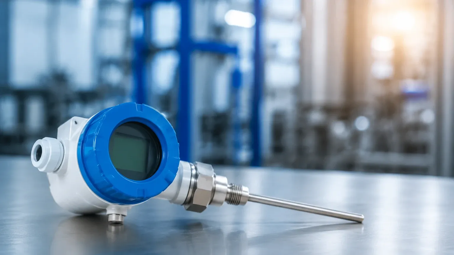
In the landscape of industrial process automation, temperature measurement is as fundamental as pressure or flow. An e&h temperature transmitter serves as the critical bridge between the raw sensing element—typically a Resistance Temperature Detector (RTD) or a Thermocouple (TC)—and the control system. By converting low-level sensor signals into a robust, standardized output such as 4-20 mA, HART, or PROFIBUS, these transmitters ensure that thermal data remains accurate and immune to electrical noise over long distances.
For engineers managing complex fluid systems, temperature data is rarely an isolated variable. It is often the primary factor used to compensate for density changes in hydrostatic level measurement or to calculate the speed of sound in ultrasonic level applications. Understanding the selection, installation, and operation of these transmitters is essential for maintaining process integrity.
Measurement Principles: RTD vs. Thermocouple
Before selecting an e&h temperature transmitter, it is necessary to understand the two primary sensing technologies it must support. The transmitter’s role is to linearize these signals and provide cold-junction compensation or lead-wire resistance correction.
Resistance Temperature Detectors (RTD)
RTDs operate on the principle that the electrical resistance of a metal increases as its temperature rises. The most common type is the Pt100, which has a resistance of 100 ohms at 0°C (32°F).
* Accuracy: High stability and repeatability.
* Range: Typically used for temperatures between -200°C and +600°C (-328°F to 1,112°F).
* Transmitter Requirement: The transmitter must account for the resistance of the lead wires. High-performance transmitters use 3-wire or 4-wire connections to cancel out this error.
Thermocouples (TC)
Thermocouples consist of two dissimilar metal wires joined at one end (the sensing junction). When there is a temperature gradient between the sensing junction and the reference junction, a small voltage is produced (the Seebeck effect).
* Accuracy: Lower than RTDs but capable of measuring much higher temperatures.
* Range: Can exceed 1700°C (3,092°F) depending on the type (Type K, J, S, etc.).
* Transmitter Requirement: The transmitter must perform "Cold Junction Compensation" (CJC) to account for the temperature at the transmitter terminals, ensuring the voltage reading reflects only the process temperature.
Architecture of an E&H Temperature Transmitter
Transmitters are categorized by their physical form factor, which dictates where they are installed within the plant architecture. Modern digital transmitters, such as those in the iTEMP line, offer modularity and advanced diagnostics.
Head-Mounted Transmitters
These are compact circular units designed to fit directly inside the terminal head of a temperature sensor assembly (Form B). This proximity to the sensor minimizes the distance that low-level signals must travel, significantly reducing the risk of electromagnetic interference (EMI).
DIN Rail Mounted Transmitters
Installed within a control cabinet or junction box, these units are ideal when the sensor environment is too hot, vibrating, or corrosive for a head-mounted unit. They allow for easy access during maintenance without entering the process field.
Field-Mounted Transmitters
Designed for the harshest environments, field-mounted transmitters are housed in robust, dual-compartment enclosures (often aluminum or stainless steel). They frequently feature integrated backlit displays, allowing operators to view the process temperature and device status directly at the measurement point.
Selection Criteria for Industrial Applications
Choosing the right e&h temperature transmitter requires an evaluation of the process environment and the required data integration. The following table provides a comparison of key selection factors:
| Feature | Head-Mounted | DIN Rail | Field-Mounted |
| :— | :— | :— | :— |
| Installation Location | Sensor Head | Control Cabinet | Process Field |
| Environmental Protection | Depends on sensor head | IP20 (requires cabinet) | IP66/IP67 |
| Local Display | No | No | Yes (Optional) |
| Signal Output | 4-20 mA / HART | 4-20 mA / HART / Bus | 4-20 mA / HART / Bus |
| Maintenance Access | Moderate | High | High |
| Vibration Resistance | High | Low | Very High |
Communication Protocols
While the 4-20 mA analog signal remains the industry standard, digital communication provides significantly more insight:
* HART: Overlays a digital signal on the analog loop, allowing for remote configuration and diagnostics.
* PROFIBUS/Foundation Fieldbus: Provides high-speed digital integration for complex automation architectures.
* WirelessHART: Eliminates the need for signal wiring, making it cost-effective for remote tanks or mobile equipment.
The Critical Link: Temperature and Level Measurement
In many industrial setups, temperature measurement is a secondary but vital input for level instrumentation. On the Welk Main Page, you can find various level measurement technologies that rely on accurate temperature data for precision.
1. Hydrostatic Level: The pressure exerted by a liquid column is dependent on its density. Since density changes with temperature, a transmitter must provide temperature data to the PLC to calculate the true level.
2. Ultrasonic Level: The speed of sound through air or gas changes by approximately 0.17% per degree Celsius. Without an integrated or external temperature sensor and transmitter, ultrasonic readings will drift significantly as the ambient temperature fluctuates.
3. Radar Level: While radar is largely unaffected by temperature, extreme thermal gradients can affect the mechanical integrity of the tank or the dielectric constant of certain vapors, requiring monitoring to ensure consistent performance.
Installation Considerations and Best Practices
Proper installation is the difference between a reliable measurement and constant troubleshooting. When deploying an e&h temperature transmitter, consider the following:
Thermowell Selection
Transmitters are rarely in direct contact with the process fluid. Instead, the sensor is inserted into a thermowell—a protective tube. The thermowell must be sized to withstand the flow-induced vibration (Wake Frequency Calculation) and the chemical corrosivity of the medium.
Wiring and Grounding
* Shielded Cables: Always use twisted-pair shielded cables for signal transmission to prevent RFI/EMI interference.
* Grounding: The shield should be grounded at only one point (usually the control system side) to avoid ground loops.
* Sensor Matching: High-end transmitters allow for "Sensor-Transmitter Matching" (Callendar-Van Dusen constants), which calibrates the transmitter to the specific resistance characteristics of the individual RTD, significantly increasing system accuracy.
Environmental Limitations
While field-mounted transmitters are rugged, they have ambient temperature limits (typically -40°C to +85°C). In extreme heat, remote mounting or the use of neck extensions on the sensor assembly is required to protect the transmitter electronics from process heat conduction.
Maintenance and Troubleshooting
Modern transmitters include self-diagnostic suites that can identify common failures before they cause a process shutdown.
* Sensor Break Detection: If an RTD wire snaps or a thermocouple burns out, the transmitter can be configured to drive the output to a specific "failsafe" value (e.g., 21.5 mA or 3.6 mA).
* Corrosion Monitoring: Some digital transmitters can detect increasing resistance in the sensor circuit, which often indicates terminal corrosion or moisture ingress.
* Drift Check: Periodically comparing the transmitter output against a calibrated reference bath is necessary to ensure long-term accuracy, especially in regulated industries like food and beverage or pharmaceuticals.
Frequently Asked Questions (FAQ)
Q: Can I use a thermocouple transmitter with an RTD sensor?
A: Most modern e&h temperature transmitters are "universal," meaning they can be configured via software or a handheld communicator to accept either RTD or TC inputs. However, you must check the specific model's datasheet.
Q: What is the benefit of a dual-input transmitter?
A: Dual-input transmitters can accept two sensors simultaneously. This allows for differential temperature measurement, average temperature calculation, or "sensor backup," where the transmitter automatically switches to the second sensor if the first one fails.
Q: How often should a temperature transmitter be calibrated?
A: In standard industrial applications, a calibration check every 12 to 24 months is typical. However, in critical safety loops or high-precision chemical processes, annual or semi-annual calibration may be required.
Q: Does the transmitter need a separate power supply?
A: Most industrial transmitters are "loop-powered" (2-wire), meaning they draw the small amount of power they need directly from the 4-20 mA signal loop provided by the control system.
By integrating reliable temperature transmitters with advanced level measurement solutions, operators can achieve a higher level of process transparency and safety. For more information on how temperature integration improves level accuracy, consult the technical resources available on the Welk Main Page.