E0471
E0471
In the field of industrial automation and process control, precision is not merely a preference but a requirement for safety and efficiency. Among the various diagnostic messages that engineers and technicians encounter when managing level measurement systems, the E0471 status code represents a critical point of intervention. This technical guide explores the implications of E0471 within the context of modern level measurement technologies, providing a framework for understanding, troubleshooting, and preventing signal-related failures in industrial environments.
Industrial level measurement relies on the consistent transmission and reception of signals—whether they are electromagnetic, sonic, or pressure-based. When a system triggers an E0471 alert, it typically indicates a "Signal Lost" or "Echo Loss" condition. This means the processing unit of the instrument can no longer identify a valid return signal from the surface of the material being measured. To address this effectively, one must first understand the underlying physics of the instruments involved and the environmental factors that influence their performance.
Principles of Industrial Level Measurement
Before addressing specific error codes like E0471, it is essential to review the measurement principles utilized by Welk and other professional manufacturers. Each technology has unique strengths and vulnerabilities regarding signal integrity.
Radar Level Measurement (GWR and Non-Contact)
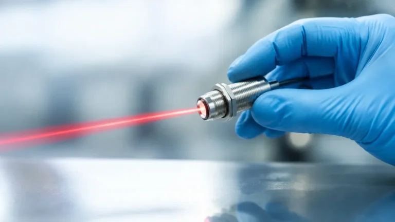
Radar level meters operate on the Time-of-Flight (ToF) principle. High-frequency microwave pulses are emitted from the antenna, travel to the product surface, and are reflected back. The distance is calculated based on the time interval between transmission and reception.
* Non-Contact Radar: Uses FMCW (Frequency Modulated Continuous Wave) or pulse technology. It is ideal for corrosive or high-temperature liquids because the sensor does not touch the medium.
* Guided Wave Radar (GWR): Directs the microwave pulse along a probe or cable. This method is highly effective for materials with low dielectric constants or in applications with heavy steam and foam, as the probe concentrates the energy.
Ultrasonic Level Sensors
Ultrasonic sensors emit high-frequency sound waves. Like radar, they use the ToF principle. However, because sound requires a medium (air) to travel, these sensors are sensitive to changes in air temperature, pressure, and the presence of heavy vapors or dust, which can attenuate the sound wave and lead to an E0471 condition.
Hydrostatic Level Transmitters
Hydrostatic measurement is based on the principle that the pressure at a specific depth in a liquid is proportional to the height of the liquid column above it. While less prone to "signal loss" in the way radar is, these sensors can face communication errors or diaphragm fouling that mimic signal interruptions in digital control systems.
Understanding the E0471 Error Condition
The E0471 code is most frequently associated with radar and ultrasonic instruments. It signifies that the signal-to-noise ratio has dropped below a critical threshold. The "echo" has either been absorbed, scattered, or blocked before it could return to the sensor's receiver.
Common Causes of E0471
1. Surface Turbulence: In tanks with high-speed agitators or heavy inflow, the surface of the liquid becomes uneven. This causes the radar or ultrasonic signal to scatter in multiple directions rather than reflecting directly back to the antenna.
2. Foam Accumulation: Certain types of foam are highly absorbent to microwave and sonic energy. If a thick layer of foam develops, the signal may be completely attenuated, triggering an E0471 alert.
3. Antenna Buildup: In chemical or wastewater applications, material can crystallize or condense on the sensor face. This "clogging" creates a false near-field reflection or dampens the emitted pulse.
4. Internal Obstructions: Pipes, ladders, or heating coils within a vessel can create parasitic reflections. If the software cannot distinguish the true level from these obstructions, it may default to an error state.
5. Low Dielectric Constant: For radar meters, materials with a dielectric constant (Er) below 1.4 reflect very little energy. Without proper sensitivity adjustment, the meter may lose the signal entirely.
Selection Criteria for Reliable Measurement
To minimize the occurrence of E0471 and ensure long-term operational stability, engineers must select the appropriate technology based on the specific process conditions. The following table provides a comparison of technologies and their resilience to common signal-loss factors.
| Technology | Turbulence Resistance | Foam Tolerance | Dust/Vapor Handling | Recommended Application |
| :— | :— | :— | :— | :— |
| 80GHz Radar | High | Moderate | Excellent | Small vessels, corrosive chemicals |
| Guided Wave Radar | Excellent | High | Good | Low dielectric liquids, bypass pipes |
| Ultrasonic | Low | Low | Moderate | Water treatment, open channels |
| Hydrostatic | N/A (Pressure-based) | High | Excellent | Deep wells, vented tanks |
| Magnetic Gauge | Excellent | Excellent | Excellent | High-pressure boilers, oil/gas |
Selecting the right instrument involves consulting a comprehensive Main Page of technical specifications to match the sensor frequency and mounting type to the vessel geometry.
Installation Guidelines to Prevent Signal Loss
Proper installation is the most effective way to prevent E0471 errors. Even the most advanced radar level meter will fail if it is poorly positioned.
1. Avoid the Center of the Tank
In cylindrical tanks with arched tops, mounting the sensor in the exact center can cause multiple reflections to converge, creating a "focal point" effect that confuses the signal processor. It is generally recommended to install the sensor at 1/2 to 1/3 of the tank radius from the wall.
2. Nozzle Design
The mounting nozzle should be as short as possible. If the nozzle is too long or narrow, the signal may reflect off the internal edges of the pipe before it even enters the tank. For radar meters, the antenna should ideally extend 10 mm (0.4 in) beyond the bottom of the nozzle.
3. Beam Angle and Obstructions
Every sensor has a specific beam angle (e.g., 3°, 8°, or 10°). Ensure that no internal structures like ladders or spray balls intersect this beam. If obstructions are unavoidable, many modern instruments allow for "False Echo Suppression," where the meter is taught to ignore reflections at specific distances.
4. Stilling Wells and Bypass Pipes
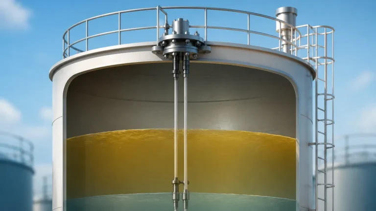
In applications with extreme turbulence or heavy foam, installing the sensor inside a stilling well or a side-mounted bypass pipe can provide a calm surface for measurement. This physically protects the signal path and eliminates the risk of E0471 caused by surface agitation.

Troubleshooting E0471 in the Field
When an E0471 error appears on a transmitter display or PLC (Programmable Logic Controller), follow these diagnostic steps:
* Verify Power Supply: Ensure the loop power is sufficient. For 4-20mA HART devices, a minimum voltage (typically 12-18V DC at the terminals) is required to maintain signal processing under load.
* Clean the Transducer: Safely depressurize the vessel if necessary and check the antenna or sensor face for buildup, moisture, or corrosion. Clean with a soft cloth and compatible solvent.
* Check the Echo Curve: Use manufacturer software to view the echo profile. A "flat line" indicates total signal loss, while multiple small peaks may indicate interference that requires re-mapping.
* Adjust Sensitivity/Threshold: If the material has a low dielectric constant, increasing the gain or decreasing the evaluation threshold may allow the device to lock onto a weak signal.
* Evaluate Process Changes: Determine if the error coincides with a change in the process, such as a new chemical additive that causes foaming or an increase in operating temperature that creates heavy steam.
Technical Limitations and Considerations
While advanced signal processing has reduced the frequency of E0471 errors, certain physical limitations remain. For instance, ultrasonic sensors cannot operate in a vacuum because sound waves require a medium. Similarly, non-contact radar may struggle with extremely low-density powders unless a high-gain antenna is used.
In high-pressure environments (above 40 bar / 580 PSI) or extreme temperatures (above 250°C / 482°F), the physical properties of the air or vapor space can change significantly. This can affect the speed of the signal or cause signal bending (refraction). In these specialized cases, hydrostatic or magnetic level gauges are often preferred as primary or redundant systems.
Frequently Asked Questions (FAQ)
Q: Can E0471 be caused by a software glitch?
A: While rare, a firmware mismatch or a corrupted configuration file can cause the device to fail to process signals. Always ensure the device is running the latest stable firmware version provided by the manufacturer.
Q: Does the E0471 error automatically reset?
A: In most modern instruments, the error will clear automatically once a valid echo is regained. However, some safety-instrumented systems (SIS) may require a manual reset or a power cycle to acknowledge the fault.
Q: How does cable length affect signal integrity?
A: For remote-mounted sensors, excessive cable length or poor shielding can introduce electromagnetic interference (EMI). This noise can mask the true echo, leading to a signal loss error. Use twisted-pair shielded cables for all industrial installations.
Q: Will a higher frequency radar (e.g., 80GHz) prevent E0471?
A: Generally, yes. Higher frequency radar has a narrower beam and better focus, which helps avoid internal obstructions and provides a stronger reflection from the material surface. However, it may be more sensitive to heavy dust than lower frequency (26GHz) models.
Conclusion
The E0471 diagnostic is a vital tool for maintaining the health of industrial level measurement loops. By understanding the interaction between the sensor's signal and the process environment, engineers can move beyond reactive troubleshooting to proactive system design. Whether through the selection of high-frequency radar for complex geometries or the implementation of stilling wells for turbulent liquids, the goal remains the same: ensuring a clear, uninterrupted signal for reliable process control. For further technical details on specific hardware configurations and application-specific advice, engineers are encouraged to review the product options and application support available on the manufacturer's official digital resources.