Coolant Flow Meter
Coolant Flow Meter
In industrial thermal management, the coolant flow meter serves as a critical diagnostic tool, ensuring that heat exchange processes remain within safe operational parameters. Whether cooling a high-speed CNC spindle, a power plant transformer, or a chemical reactor, the ability to monitor the volume and velocity of cooling media is essential for preventing equipment failure and optimizing energy consumption.
Welk, a professional manufacturer of industrial measurement instruments, provides high-precision solutions designed to withstand the rigors of industrial environments. While level measurement is vital for monitoring coolant reservoirs—as detailed on our Main Page—flow measurement provides the real-time data necessary to confirm that the cooling medium is actually reaching its destination at the required rate.
Understanding Coolant Flow Measurement Principles
Before selecting a coolant flow meter, it is necessary to understand the physical principles that govern different measurement technologies. Most industrial coolants are either water-based (often with glycol additives) or oil-based. The choice of measurement principle depends largely on the fluid's properties, such as conductivity, viscosity, and cleanliness.
Electromagnetic Principle (Faraday’s Law)
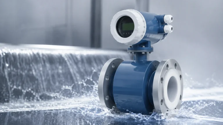
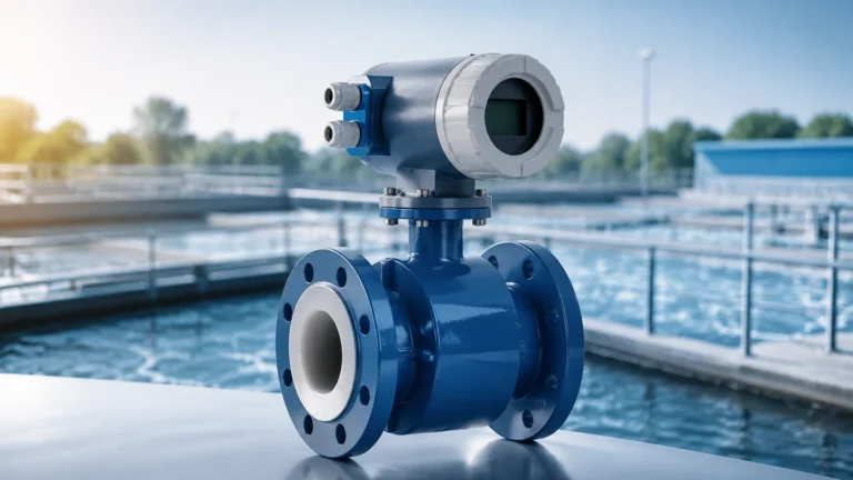
Electromagnetic flow meters, or magmeters, operate based on Faraday’s Law of Electromagnetic Induction. This law states that a conductor moving through a magnetic field produces an electrical signal. In this application, the conductive coolant (typically water-based) acts as the conductor. As the fluid flows through a magnetic field generated by the meter’s coils, electrodes pick up a voltage proportional to the flow velocity.
Ultrasonic Principle (Transit-Time)
Ultrasonic meters use sound waves to determine flow velocity. Transit-time ultrasonic meters employ two transducers that act as both transmitters and receivers. They send signals back and forth through the fluid. When the fluid is moving, the signal traveling downstream moves faster than the signal traveling upstream. The difference in time ($Δt$) is directly proportional to the flow rate.
Vortex Shedding Principle
Based on the Karman Vortex Street effect, these meters place a "shedder bar" in the flow path. As coolant flows past this obstruction, vortices (swirls) are shed alternately on each side. The frequency of these vortices is directly proportional to the fluid velocity over a wide range of Reynolds numbers.
Turbine Principle
A turbine flow meter utilizes the mechanical energy of the flowing coolant to rotate a rotor positioned in the flow stream. The rotational speed of the rotor is proportional to the velocity of the fluid. This rotation is typically sensed by a magnetic pickup located outside the flow tube, which generates a frequency signal.
Key Technologies for Coolant Monitoring
Different industrial applications require specific technological strengths. Below is an evaluation of the most common technologies used for coolant flow monitoring.
1. Electromagnetic Flow Meters
These are the "gold standard" for water-based coolant systems. Because they have no moving parts and no obstructions in the flow path, they offer zero pressure drop and require minimal maintenance.
* Best for: Water/glycol mixtures with conductivity > 5 μS/cm.
* Limitation: Cannot measure oil-based coolants or deionized water with zero conductivity.
2. Ultrasonic Flow Meters (Clamp-on)
Clamp-on ultrasonic meters are highly valued for retrofit applications where cutting into existing piping is not feasible. They are mounted on the exterior of the pipe, making them ideal for high-pressure systems or systems where contamination must be avoided.
* Best for: Temporary measurements, large pipe diameters, and non-conductive fluids.
* Limitation: Requires a clean fluid; high concentrations of bubbles or solids can scatter the signal.
3. Vortex Flow Meters
Vortex meters are exceptionally robust and can handle high temperatures and pressures. They are often used in primary cooling loops for heavy machinery.
* Best for: High-velocity flows and high-temperature liquids.
* Limitation: Not suitable for low-flow applications, as a minimum velocity is required to generate detectable vortices.
Selection Criteria for Industrial Coolant Systems
Selecting the correct coolant flow meter requires a comprehensive analysis of the process conditions. Engineers should use the following table as a baseline for technology comparison:
| Feature | Electromagnetic | Ultrasonic (Transit-time) | Vortex | Turbine |
| :— | :— | :— | :— | :— |
| Fluid Type | Conductive liquids | Clean liquids | Liquids/Gases | Clean, low-viscosity |
| Accuracy | ±0.5% of rate | ±1.0% to ±2.0% | ±1.0% | ±0.25% to ±0.5% |
| Pressure Drop | None | None | Moderate | High |
| Moving Parts | No | No | No | Yes |
| Typical Turn-down | 100:1 | 50:1 | 20:1 | 10:1 |
| Maintenance | Very Low | Low | Low | Moderate |
Critical Factors to Confirm:
1. Conductivity: If using a magmeter, confirm the coolant's conductivity. Pure deionized water or oil-based coolants will require ultrasonic or mechanical meters.
2. Viscosity: High-viscosity coolants (certain oils) may affect the Reynolds number, potentially making vortex meters inaccurate.
3. Temperature and Pressure: Standard coolant loops operate between 10°C and 80°C (50°F to 176°F), but specialized industrial processes may exceed 200°C (392°F), requiring high-temperature sensors.
4. Pipe Material: For ultrasonic clamp-on meters, the pipe material (e.g., carbon steel, stainless steel, PVC) and wall thickness must be known to calibrate the sound path correctly.
Installation Best Practices and Pipe Requirements
Proper installation is the single most important factor in ensuring the accuracy of a coolant flow meter. Even the most expensive instrument will fail to provide reliable data if installed in a location with turbulent flow.
Straight Pipe Runs
Most flow meters require a certain length of straight pipe before (upstream) and after (downstream) the sensor to stabilize the flow profile. A common engineering standard is the "10D/5D rule":
* Upstream: 10 times the nominal pipe diameter (e.g., for a 50 mm pipe, 500 mm of straight run).
* Downstream: 5 times the nominal pipe diameter (e.g., 250 mm of straight run).
If the installation point follows a pump, valve, or 90-degree elbow, the upstream requirement may increase to 20D or more.
Orientation and Filling
The meter must always be completely full of liquid. For this reason:
* Vertical Installation: Flow should move upward. This ensures the pipe remains full and prevents air bubbles from being trapped at the sensor head.
* Horizontal Installation: Avoid placing sensors at the very top of a pipe (where air pockets collect) or the very bottom (where sediment may settle). A 3 o'clock or 9 o'clock position is preferred for electrodes in magmeters.
Grounding
For electromagnetic flow meters, proper grounding is essential to eliminate electrical noise. The fluid, the meter body, and the adjacent piping should all be at the same electrical potential. In plastic piping systems, grounding rings are required to establish this connection.
Managing Risks: Fouling, Air Pockets, and Cavitation
Industrial coolant systems are rarely "perfect" environments. Engineers must design for several common risks that can degrade meter performance over time.
1. Scaling and Fouling
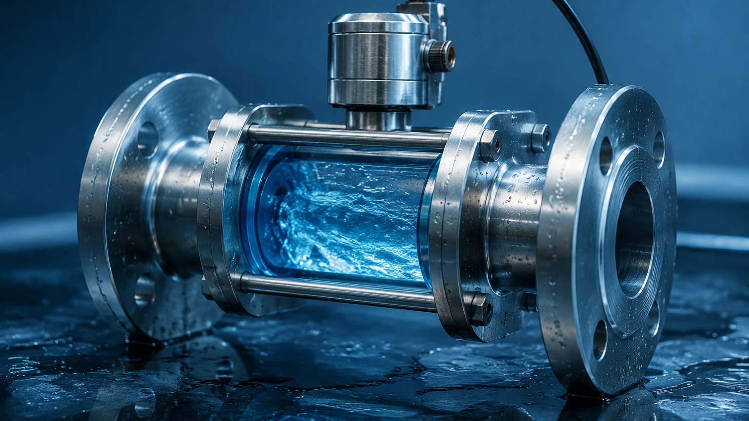
In open-loop cooling towers or systems using hard water, mineral deposits (scaling) can build up on the interior of the flow meter. In magmeters, scaling on the electrodes can insulate them from the fluid, leading to signal loss. Regular inspection and the use of ultrasonic cleaning features or non-stick liners (like PTFE) can mitigate this risk.
2. Entrained Air and Bubbles
Air bubbles are the enemy of flow accuracy. In ultrasonic meters, bubbles scatter the sound waves, causing "signal drop." In magmeters, air is non-conductive; if a large bubble passes an electrode, it may cause the reading to spike or drop to zero. Always install flow meters at low points in the piping or after an air-release valve.
3. Cavitation
If the pressure in the cooling loop drops too low (often after a control valve or at a pump inlet), the fluid may vaporize, forming cavities (bubbles). When these bubbles collapse downstream, they can cause physical damage to turbine blades or vortex shedder bars. Ensure the system pressure remains well above the vapor pressure of the coolant at the operating temperature.
Frequently Asked Questions (FAQ)
Q: Can I use a water flow meter for a 50/50 glycol mix?
A: Yes, but you must account for the change in physical properties. Glycol is more viscous and has a different specific heat than pure water. For electromagnetic meters, as long as the mix remains conductive, the velocity measurement is accurate, but the mass flow calculation (if performed by the meter) must be adjusted for the higher density.
Q: How often should a coolant flow meter be calibrated?
A: For most industrial applications, an annual calibration check is recommended. However, in critical cooling applications (like data centers or nuclear reactors), semi-annual verification may be required by safety protocols.
Q: Why is my ultrasonic flow meter giving an "E1" or "Low Signal" error?
A: This is usually due to poor acoustic coupling between the transducer and the pipe, or the presence of air bubbles in the coolant. Re-applying acoustic couplant gel or moving the sensors to a vertical pipe section often resolves the issue.
Q: Is a flow meter enough to protect my system?
A: While a flow meter confirms movement, it does not confirm the volume of the reservoir. For complete system integrity, we recommend pairing flow meters with hydrostatic or radar level transmitters. You can explore these complementary technologies on our Main Page.
Conclusion
A coolant flow meter is more than just a monitoring device; it is a safeguard for industrial productivity. By understanding the measurement principles—whether electromagnetic, ultrasonic, or vortex—and adhering to strict installation guidelines regarding straight pipe runs and orientation, facilities can ensure their cooling systems operate at peak efficiency. When selecting an instrument, always prioritize the fluid's conductivity and the potential for fouling to ensure long-term reliability in the field.