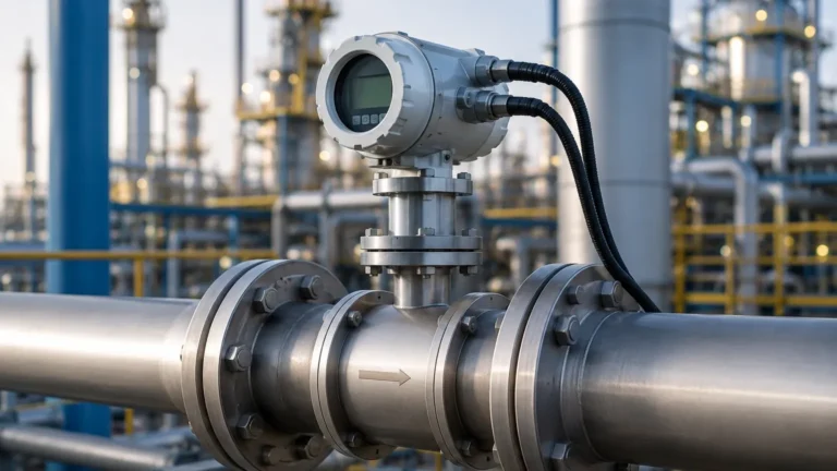
Electric Pressure Sensor
Electric Pressure Sensor
In the landscape of industrial automation and process control, the electric pressure sensor serves as a fundamental component for monitoring, controlling, and safety management. These devices, often referred to as pressure transducers or transmitters, convert mechanical pressure into a standardized electrical signal. For engineers and facility managers, understanding the nuances of these sensors is critical for ensuring the accuracy of data in applications ranging from simple water tank monitoring to complex chemical processing.
As a professional manufacturer, Welk provides a comprehensive range of industrial level and pressure measurement instruments designed to meet the rigorous demands of global industries. By integrating advanced sensing technologies, these instruments offer the reliability required for high-stakes environments. For more detailed technical specifications and product ranges, professionals can visit the Main Page to explore specific solutions for their operational needs.
Measurement Principles of Electric Pressure Sensors
Before selecting an electric pressure sensor, it is essential to understand the underlying physical principles that govern their operation. Most industrial sensors rely on the deformation of a sensing element, which is then translated into an electrical change.
Piezoresistive Sensors
Piezoresistive technology is perhaps the most common principle used in industrial pressure measurement. These sensors utilize a diaphragm (typically made of silicon or stainless steel) with integrated strain gauges. When pressure is applied, the diaphragm deforms, causing a change in the electrical resistance of the strain gauges. This change is measured using a Wheatstone bridge circuit. Piezoresistive sensors are highly sensitive and offer excellent linearity over a wide range of pressures.
Capacitive Sensors
Capacitive pressure sensors measure the change in electrical capacitance between a flexible diaphragm and a fixed metal plate. As pressure moves the diaphragm, the distance between the plates changes, thereby altering the capacitance. These sensors are known for their high sensitivity, particularly in low-pressure applications, and their ability to withstand significant overpressure without permanent damage.
Piezoelectric Sensors
Unlike piezoresistive sensors, piezoelectric sensors utilize materials (such as quartz or certain ceramics) that generate an electric charge when subjected to mechanical stress. These are primarily used for dynamic pressure measurements, such as detecting pressure spikes or pulsations in high-speed processes, rather than static pressure monitoring.
Resonant Wire Sensors
This technology uses a wire vibrating at its resonant frequency. As pressure is applied to a diaphragm, it changes the tension of the wire, which in turn shifts its resonant frequency. This shift is detected electronically and converted into a pressure reading. These sensors are valued for their high precision and long-term stability.
The Relationship Between Pressure and Level Measurement
In many industrial contexts, an electric pressure sensor is utilized specifically for level measurement via the hydrostatic principle. This method relies on the fact that the pressure at the bottom of a liquid column is directly proportional to the height of the liquid and its density.
The formula used is:
P = ρ × g × h
Where:
* P is the hydrostatic pressure (Pa).
* ρ (rho) is the density of the liquid (kg/m³).
* g is the acceleration due to gravity (approximately 9.81 m/s²).
* h is the height of the liquid column (m).
By measuring the pressure at a fixed point (usually the bottom of a tank), the electric pressure sensor can provide a continuous level reading. This is particularly effective in vented tanks where atmospheric pressure is balanced. In pressurized tanks, a differential pressure sensor is required to subtract the overhead gas pressure from the total pressure at the bottom.
Key Evaluation Criteria for Selection
Selecting the correct electric pressure sensor requires a detailed analysis of the process environment. Engineers should confirm the following parameters before procurement:
1. Pressure Type: Determine if the application requires gauge pressure (referenced to atmospheric pressure), absolute pressure (referenced to a vacuum), or differential pressure (the difference between two points).
2. Measurement Range: The sensor should be selected so that the operating pressure falls within 50% to 75% of the sensor's full-scale range to ensure longevity and accuracy.
3. Media Compatibility: The wetted parts (diaphragm and housing) must be chemically compatible with the process fluid. Common materials include 316L stainless steel, ceramic, Hastelloy, or Tantalum for corrosive media.
4. Output Signal: Standard industrial outputs include 4-20 mA (current loop), 0-10 VDC, or digital protocols such as RS485 Modbus or HART. 4-20 mA is generally preferred for long-distance transmission due to its resistance to electrical noise.
5. Accuracy Requirements: This includes linearity, hysteresis, and repeatability. For most industrial level applications, an accuracy of 0.25% to 0.5% FS (Full Scale) is standard.
Technology Selection Table
| Sensor Technology | Best For | Advantages | Limitations |
| :— | :— | :— | :— |
| Piezoresistive | General purpose, Oil & Gas | High sensitivity, compact size | Sensitive to temperature fluctuations |
| Capacitive | Low pressure, Food & Beverage | Robust, high overpressure limit | Larger physical size than silicon sensors |
| Ceramic Thick Film | Corrosive chemicals | Excellent chemical resistance | Lower sensitivity than silicon |
| Resonant Wire | High precision labs | Extremely stable over time | Higher cost and complex electronics |
Installation Considerations
Proper installation is as important as sensor selection. Incorrect mounting can lead to measurement errors or premature device failure.
* Mounting Position: For liquid applications, the sensor should ideally be mounted below the minimum level to ensure the diaphragm is always in contact with the fluid. For gas applications, mounting above the source helps prevent condensate from collecting on the sensor face.
* Impulse Piping: If using impulse lines to connect the sensor to the process, ensure they are sloped correctly (typically 1:12) to allow air bubbles or condensate to escape back into the process.
* Atmospheric Venting: Gauge pressure sensors require a vent path (usually through a breathable desiccant-filled tube in the cable) to compensate for changes in barometric pressure. Ensure this vent is not blocked or submerged.
* Electrical Grounding: To prevent interference from electromagnetic fields (EMI), ensure the sensor housing and cable shielding are properly grounded according to local electrical codes.
Common Risks and Limitations
While an electric pressure sensor is a reliable tool, it is not without limitations. Awareness of these risks allows for better system design:
* Density Sensitivity: Since hydrostatic level measurement depends on liquid density, any change in the temperature or composition of the liquid that affects density will result in a level error. If the liquid density varies significantly, temperature compensation or a different measurement technology (like radar) may be required.
* Clogging and Buildup: In applications involving slurries or viscous liquids, the pressure port or diaphragm can become clogged. In these cases, a flush-diaphragm sensor is recommended to prevent material accumulation.
* Pressure Surges (Water Hammer): Rapidly closing valves can create pressure spikes that far exceed the sensor's burst pressure. Utilizing a pressure snubber or choosing a sensor with high overpressure protection can mitigate this risk.
* Thermal Drift: All electronic sensors experience some degree of drift when exposed to temperature extremes. It is vital to check the operating temperature range and the thermal error coefficient in the manufacturer's datasheet.
Frequently Asked Questions (FAQ)
Q: How often should an electric pressure sensor be calibrated?
A: Calibration frequency depends on the criticality of the process and the stability of the sensor. Typically, industrial sensors are calibrated annually. However, in harsh environments or high-precision applications, semi-annual checks may be necessary.
Q: Can a pressure sensor be used to measure the level of a boiling liquid?
A: It is challenging. Boiling liquids have fluctuating densities due to vapor bubbles, and the turbulent surface can cause signal noise. Additionally, the vapor pressure in the headspace must be accounted for using a differential pressure setup.
Q: What is the difference between a pressure transducer and a pressure transmitter?
A: While the terms are often used interchangeably, a transducer typically outputs a low-level voltage signal (e.g., millivolts), whereas a transmitter includes signal conditioning electronics to provide a standardized high-level output like 4-20 mA.
Q: Why is 4-20 mA the industry standard for these sensors?
A: The 4-20 mA current loop is robust against voltage drops over long cable runs and provides an inherent "live zero" (4 mA). If the signal drops to 0 mA, the system immediately knows there is a wire break or sensor failure.
Conclusion
The electric pressure sensor is a versatile and essential tool in modern industrial automation. Whether used for direct pressure monitoring or as a proxy for liquid level, its selection must be guided by a thorough understanding of the process media, environmental conditions, and required electrical outputs. By adhering to proper installation practices and acknowledging the physical limitations of the technology, engineers can ensure long-term accuracy and safety. For those seeking high-performance instrumentation and customized OEM/ODM services, Welk offers a range of solutions tailored to water treatment, chemical processing, and industrial automation. Detailed product information and technical support are available through our Main Page.