Endress and Hauser Greenwood
Endress and Hauser Greenwood
The industrial landscape of the United States relies heavily on the precision of process automation, and few locations are as central to this mission as the Endress and Hauser Greenwood campus in Indiana. Serving as the North American headquarters for one of the world's leading instrumentation firms, the Greenwood facility is more than just an administrative hub; it is a center for manufacturing, calibration, and technical education. For process engineers and plant managers, understanding the capabilities emerging from this region provides a benchmark for level measurement excellence across the water treatment, chemical, and oil and gas sectors.
In the realm of B2B industrial procurement, the choice of level measurement technology is often dictated by the standards established by industry leaders. The Greenwood site is particularly noted for its Process Training Units (PTUs), which allow technicians to experience real-world scenarios in a controlled environment. This commitment to technical proficiency underscores the importance of selecting the right measurement principle for specific applications. Whether a facility is managing volatile chemicals or municipal wastewater, the principles of radar, ultrasonic, and hydrostatic measurement remain the foundation of operational safety and efficiency.
The Significance of the Greenwood Hub for Process Automation
Endress and Hauser Greenwood represents a significant investment in the domestic production of high-accuracy sensors. By localizing manufacturing for the North American market, the facility reduces lead times and ensures that instruments are built to regional standards, such as ANSI and ASME. The campus includes specialized laboratories for flow, level, pressure, and temperature calibration, ensuring that every device meets stringent NIST-traceable requirements.
For the engineering community, the presence of such a facility in the Midwest serves as a technical resource. It facilitates a deeper understanding of how different media—ranging from liquids with low dielectric constants to corrosive slurries—interact with sensing elements. This knowledge is critical when transitioning from theoretical models to practical field installations. When evaluating your facility's needs, it is helpful to Review product options and application support on the Main Page to compare these industry-standard technologies with specialized OEM solutions.
Fundamental Level Measurement Principles
Before selecting an instrument, it is essential to understand the physics behind the measurement. Industrial level sensors generally fall into two categories: contact and non-contact. Each has distinct advantages depending on the vessel geometry and the physical properties of the substance being measured.
Radar Level Measurement (Time-of-Flight)
Radar technology is the gold standard for many high-precision applications. It operates on the Time-of-Flight (ToF) principle. The sensor emits a high-frequency electromagnetic pulse (typically in the 6 GHz to 80 GHz range) toward the product surface. The pulse is reflected back to the antenna, and the device calculates the distance based on the time it took for the signal to travel.
* Frequency Matters: Higher frequencies (e.g., 80 GHz) allow for smaller antennas and narrower beam angles, which are ideal for tall, narrow tanks with internal obstructions. Lower frequencies (e.g., 6 GHz) are better at penetrating heavy foam or steam.
* Dielectric Constant (εr): Radar relies on the change in dielectric constant at the air-medium interface. Materials with a low εr, like hydrocarbons, reflect less energy than water-based liquids, requiring more sensitive electronics.
Ultrasonic Level Measurement
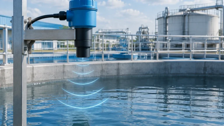
Ultrasonic sensors use sound waves instead of electromagnetic pulses. A transducer emits an ultrasonic pulse (typically 20 kHz to 70 kHz) that bounces off the liquid surface. The time taken for the echo to return determines the distance.
* Medium Dependency: Unlike radar, the speed of sound is highly dependent on air temperature. Most modern ultrasonic sensors include a temperature probe to compensate for these changes automatically.
* Limitations: Ultrasonic waves can be absorbed by heavy foam or scattered by significant turbulence, making them less suitable for aggressive chemical reactions compared to radar.
Hydrostatic Level Measurement
This is a contact-based method that measures the pressure exerted by a liquid column. The principle is simple: $P = ρgh$, where $P$ is pressure, $ρ$ is the density of the liquid, $g$ is gravity, and $h$ is the height of the liquid.
* Open vs. Closed Tanks: In open tanks, a single pressure transmitter at the bottom is sufficient. In pressurized (closed) tanks, a differential pressure (DP) transmitter is required to subtract the head pressure of the gas above the liquid.
* Reliability: Hydrostatic sensors are robust and unaffected by foam or surface turbulence, though they do require accurate knowledge of the liquid's specific gravity.
Selecting Level Instrumentation: A Comparative Analysis
Choosing between the technologies often found at the Endress and Hauser Greenwood facility involves weighing accuracy against cost and environmental constraints. The following table provides a general comparison for typical industrial applications.
| Technology | Typical Accuracy | Max Range | Contact Type | Ideal Application |
| :— | :— | :— | :— | :— |
| 80 GHz Radar | ±1 mm (0.04") | 125m (410 ft) | Non-contact | High-precision chemical storage |
| Ultrasonic | ±0.2% of range | 15m (50 ft) | Non-contact | Water/Wastewater open channels |
| Hydrostatic | ±0.1% of span | 100m (328 ft) | Contact | Deep wells and vented tanks |
| Magnetic Gauge | ±5 mm (0.2") | 6m (20 ft) | Contact | Boiler drums and oil/water separators |
When selecting a device, engineers must also consider the "Dead Zone" (or Blocking Distance). This is the area immediately below the sensor where measurement is impossible because the electronics cannot switch from transmit to receive mode fast enough. For radar, this might be only a few centimeters, whereas for ultrasonic sensors, it can be 250 mm to 500 mm (10" to 20").

Installation Best Practices for Industrial Level Sensors
Even the most advanced sensor from a premier manufacturer will fail if installed incorrectly. Proper placement is the most critical factor in achieving reliable data.
1. Nozzle Geometry: For non-contact sensors (Radar/Ultrasonic), the nozzle should be as short as possible. If the nozzle is too long or narrow, the signal may reflect off the nozzle walls rather than the liquid surface, creating a "false echo."
2. Avoid Obstructions: Do not install sensors directly above ladders, heating coils, or agitators. If obstructions are unavoidable, many modern instruments offer "False Echo Suppression," allowing the software to ignore static reflections.
3. Positioning on the Tank: Sensors should generally be placed at 1/6th to 1/4th of the tank diameter from the wall. Placing a sensor in the exact center of a domed tank can cause multiple reflections that confuse the signal processing unit.
4. Inflow Streams: Never install a level sensor directly in the path of the filling stream. The turbulence and air entrainment will cause erratic readings.
Limitations and Environmental Constraints
While the engineering support at Endress and Hauser Greenwood provides solutions for most challenges, every technology has its physical limits.
* Vapor and Gas Layers: In radar measurement, heavy vapors with high dielectric constants can slow down the signal, leading to a measurement error. Similarly, in ultrasonic measurement, certain gases (like CO2) change the speed of sound significantly compared to air.
* Vacuum Conditions: Ultrasonic sensors cannot operate in a vacuum because sound waves require a medium (air/gas) to travel. Radar, being electromagnetic, works perfectly in a vacuum.
* Temperature Extremes: High-temperature applications (above 200°C / 392°F) often require specialized cooling fins or remote electronics to protect the sensor head.
* Build-up and Coating: For contact-based methods like hydrostatic or tuning forks, viscous liquids that leave a coating can cause "drift" or false switching. In these cases, non-contact radar is usually preferred.
Frequently Asked Questions (FAQ)
Q: How often should level sensors be calibrated?
A: This depends on the industry. In regulated sectors like pharmaceuticals or food and beverage, annual calibration is standard. In general water treatment, a check every 2-3 years may suffice. Facilities like those in Greenwood offer NIST-traceable calibration services to ensure compliance.
Q: Can I use one sensor for multiple types of liquids?
A: Only if the measurement principle is independent of the liquid's properties. Radar is generally independent of density changes, but hydrostatic sensors must be recalibrated if the liquid's specific gravity changes.
Q: What is the benefit of 80 GHz radar over 26 GHz?
A: The main benefit is the beam angle. An 80 GHz radar has a much narrower beam (often around 3 degrees), which allows it to avoid internal tank obstructions and measure accurately even in narrow nozzles.
Q: How do I handle foam on the surface of the liquid?
A: Foam is a common challenge. For light foam, high-frequency radar usually penetrates to the liquid. For thick, dense foam, a hydrostatic pressure transmitter or a bypass chamber with a magnetic level gauge is often a more reliable solution.
For those seeking reliable, accurate, and cost-effective level measurement solutions, it is vital to partner with manufacturers who understand these technical nuances. Whether you are looking for high-end specialized units or versatile industrial sensors, you can Review product options and application support on the Main Page to find the right fit for your specific automation requirements.