Electromagnetic Flow Sensor
Electromagnetic Flow Sensor
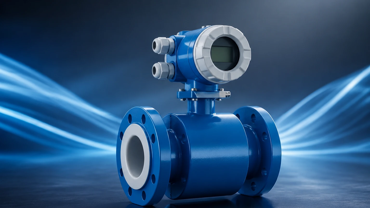
In the landscape of industrial process control, the electromagnetic flow sensor—often referred to as a magmeter—stands as one of the most versatile and reliable instruments for measuring the volumetric flow rate of conductive liquids. Unlike mechanical flow meters that rely on moving parts, electromagnetic flow sensors utilize the principles of physics to provide an unobstructed flow path, minimizing pressure drop and maintenance requirements. This article provides a comprehensive technical overview of electromagnetic flow sensors, their underlying principles, selection criteria, and practical installation guidelines for engineering professionals.
Measurement Principle: Faraday’s Law of Induction
The operation of an electromagnetic flow sensor is based on Faraday’s Law of Electromagnetic Induction. This principle states that a conductor moving through a magnetic field produces an electrical voltage proportional to the velocity of that conductor. In the context of a flow meter, the "conductor" is the process liquid itself.
To facilitate this measurement, the sensor consists of a non-magnetic tube lined with an insulating material. Two electromagnetic coils are placed outside or within the flow tube to generate a constant magnetic field ($B$) across the cross-section of the pipe. As the conductive liquid flows through this field at a certain velocity ($v$), it induces a voltage ($E$) that is picked up by two electrodes mounted flush with the pipe wall.
The relationship is defined by the formula:
$E = k \cdot B \cdot D \cdot v$
Where:
* $E$ is the induced voltage.
* $k$ is a meter constant.
* $B$ is the magnetic field strength.
* $D$ is the distance between the electrodes (internal diameter of the pipe).
* $v$ is the average velocity of the liquid.
Since $k$, $B$, and $D$ are constant for a specific sensor, the induced voltage is directly and linearly proportional to the flow velocity. The transmitter then converts this microvolt signal into a standard industrial output, such as a 4-20mA signal, pulse, or digital communication protocol (HART, Modbus, Profibus).
Key Components and Materials
Selecting the right electromagnetic flow sensor requires an understanding of its construction materials, as these must withstand the chemical and physical properties of the process medium.
1. The Liner
The liner prevents the induced voltage from short-circuiting through the metal pipe wall. Choosing the correct liner material is critical for the sensor's longevity.
| Liner Material | Temperature Range | Typical Applications |
| :— | :— | :— |
| Hard Rubber | 0°C to +70°C | Water treatment, general purpose wastewater. |
| Polyurethane (PU) | -20°C to +50°C | Abrasive slurries, sand/water mixtures. |
| PTFE (Teflon) | -20°C to +120°C | Strong acids, bases, and high-temperature chemicals. |
| PFA | -20°C to +150°C | High-temperature chemicals and vacuum applications. |
| Ceramic | -40°C to +180°C | Highly corrosive and abrasive media at high temperatures. |
2. Electrodes
Electrodes are the only parts, along with the liner, in direct contact with the fluid. They must be resistant to corrosion and chemical attack.
* Stainless Steel (316L): Standard for water and mildly corrosive liquids.
* Hastelloy C: Used for seawater and various organic/inorganic acids.
* Titanium: Ideal for chlorides and hypochlorite solutions.
* Tantalum: Reserved for highly aggressive acids like hydrochloric or sulfuric acid.
* Platinum/Iridium: Used for the most extreme chemical environments.
Selection Criteria for Industrial Applications
When evaluating an electromagnetic flow sensor for a project, several technical factors must be confirmed to ensure accuracy and reliability. For a broader view of how these sensors integrate into comprehensive monitoring systems, engineers often Review product options and application support to match flow data with level and pressure instrumentation.
Fluid Conductivity
The most fundamental requirement is that the fluid must be electrically conductive. Most magmeters require a minimum conductivity of 5 μS/cm (microsiemens per centimeter). While most water-based liquids and chemicals meet this threshold, hydrocarbons (oils, fuels) and deionized water are generally non-conductive and cannot be measured with this technology.
Pipe Size and Flow Velocity
Magmeters are available in sizes ranging from DN3 (3 mm) to DN3000 (3000 mm). For optimal accuracy, the flow velocity should typically fall between 0.5 m/s and 10 m/s. If the existing pipe velocity is too low, a smaller meter with reducers may be necessary to increase the velocity through the sensor.
Pressure and Temperature Ratings
The sensor housing and flange ratings must exceed the maximum process pressure. Similarly, the liner material must be rated for the maximum process temperature, accounting for potential Clean-in-Place (CIP) or Sterilization-in-Place (SIP) cycles in food and pharmaceutical applications.
Installation Considerations
Proper installation is paramount to achieving the specified accuracy (typically ±0.5% or ±0.25% of rate).
Straight Pipe Runs
To ensure a stable flow profile, electromagnetic flow sensors require a certain amount of straight pipe upstream and downstream of the installation point. The standard recommendation is 5D upstream (5 times the nominal pipe diameter) and 2D downstream. If there are high-turbulence elements like pumps or partially open valves, the upstream requirement may increase to 10D.
Pipe Orientation
* Vertical Installation: This is the preferred orientation, with the flow moving upward. This ensures the pipe is always full and prevents air bubbles from collecting at the electrodes.
* Horizontal Installation: The sensor must be installed in a section of the pipe that is always full. The electrodes should be positioned on the horizontal plane (3 o'clock and 9 o'clock positions) to prevent interference from air bubbles at the top or sediment at the bottom.
Grounding
Since the induced voltage is very small (often in the millivolt range), electrical noise can easily interfere with the signal. Proper grounding is essential. If the sensor is installed in a plastic or lined pipe, grounding rings must be used to provide an electrical connection to the fluid, ensuring the sensor and the fluid are at the same potential.
Limitations and Risks
While highly effective, the electromagnetic flow sensor is not a universal solution. Engineers must be aware of the following limitations:
1. Non-Conductive Fluids: As mentioned, they cannot measure oils, greases, or pure alcohols.
2. Entrained Gas: Large amounts of air or gas bubbles can cause significant measurement errors or signal loss.
3. Vacuum Conditions: Certain liners, like PTFE, can collapse or peel away from the tube wall under vacuum conditions unless specifically designed with a mechanical reinforcement (like PFA with a stainless steel mesh).
4. Coating and Scaling: If the fluid tends to leave deposits (e.g., calcium carbonate or heavy oils), the electrodes may become insulated, leading to measurement drift. In such cases, sensors with electrode cleaning circuits or removable electrodes are recommended.
Comparison with Alternative Technologies
| Feature | Electromagnetic | Ultrasonic (Transit-Time) | Vortex |
| :— | :— | :— | :— |
| Moving Parts | None | None | None |
| Pressure Drop | Negligible | Negligible | Moderate |
| Conductivity Req. | Yes (>5 μS/cm) | No | No |
| Accuracy | High (±0.5%) | Moderate (±1-2%) | Moderate (±1%) |
| Maintenance | Very Low | Low | Low |
| Media | Conductive Liquids | Clean Liquids | Liquids, Gas, Steam |
Frequently Asked Questions (FAQ)
Q: Can an electromagnetic flow sensor measure flow in both directions?
A: Yes, most modern magmeters are bi-directional. The transmitter can be configured to track forward and reverse flow separately or provide a net total.
Q: How often does a magmeter need calibration?
A: Because there are no moving parts to wear out, the calibration is very stable. In many water applications, a verification check every 1–2 years is sufficient, though regulated industries (like pharmaceutical or food) may require annual wet calibration.
Q: What happens if the pipe is only partially full?
A: Standard electromagnetic flow sensors will provide inaccurate readings if the pipe is not full, as the math assumes a constant cross-sectional area ($D$). For partially filled pipes or gravity-fed drains, specialized "partially full" magmeters with additional electrodes are required.
Q: Does fluid density or viscosity affect the measurement?
A: No. One of the primary advantages of the electromagnetic flow sensor is that the measurement is independent of density, viscosity, temperature, and pressure, provided the fluid remains conductive and the flow is turbulent or laminar within standard limits.
Conclusion
The electromagnetic flow sensor remains a cornerstone of industrial fluid measurement due to its lack of internal obstructions, high accuracy, and compatibility with aggressive chemicals. By carefully matching liner and electrode materials to the process media and adhering to strict installation guidelines regarding grounding and pipe runs, operators can achieve long-term, maintenance-free operation. For technical specifications and to explore a full range of industrial measurement solutions, visit the Main Page of Welk's industrial instrumentation catalog. Understanding these fundamental principles ensures that the selected sensor will perform reliably in even the most demanding water treatment, chemical, or mining applications.