Electromagnetic Flowmeter
Electromagnetic Flowmeter
In the landscape of industrial process control, the electromagnetic flowmeter, often referred to as a magmeter, stands as one of the most versatile and reliable instruments for measuring the volume flow of conductive liquids. Unlike mechanical flowmeters that rely on moving parts, the electromagnetic flowmeter utilizes a non-intrusive design, making it an ideal choice for applications involving corrosive chemicals, slurries, and wastewater. As a professional manufacturer, Welk provides these solutions to ensure high accuracy and long-term stability across diverse sectors including water treatment, chemical processing, and industrial automation.
Understanding the technical nuances of these instruments is essential for engineers and procurement specialists. This guide explores the measurement principles, selection criteria, and installation requirements necessary to maximize the performance of an electromagnetic flowmeter in a B2B environment.
Understanding the Measurement Principle of Electromagnetic Flowmeters
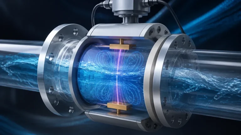
The operation of an electromagnetic flowmeter is based on Faraday’s Law of Electromagnetic Induction. This law states that a voltage is induced when a conductor moves through a magnetic field. In the context of a flowmeter, the conductive liquid itself serves as the moving conductor.
The fundamental equation governing this process is:
E = k × B × v × D
Where:
* E is the induced voltage (signal).
* k is an instrument constant.
* B is the strength of the magnetic field generated by the internal coils.
* v is the average velocity of the fluid moving through the pipe.
* D is the inner diameter of the pipe (the distance between the electrodes).
When the conductive fluid flows through the magnetic field generated by the meter’s coils, a voltage is produced that is directly proportional to the flow velocity. Two electrodes mounted on opposite sides of the flow tube pick up this voltage, which is then processed by the transmitter to calculate the volumetric flow rate. Because the measurement is independent of fluid density, viscosity, temperature, and pressure (within certain limits), the electromagnetic flowmeter offers exceptional precision, often reaching accuracies of ±0.5% or better.
Key Components and Construction
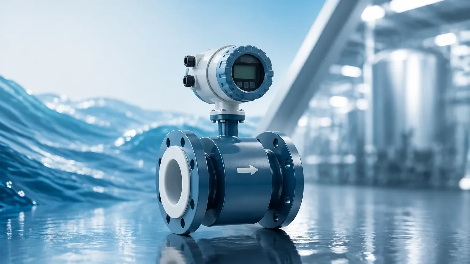
A standard electromagnetic flowmeter consists of two primary assemblies: the flow sensor (the primary element installed in the pipeline) and the transmitter (the secondary element that processes the signal).
The Sensor Body
Typically constructed from stainless steel or carbon steel, the sensor body houses the electromagnetic coils. The interior of the sensor is lined with an insulating material to prevent the induced voltage from shorting out against the metal pipe wall.
Electrodes
The electrodes are the only parts, along with the liner, in direct contact with the process fluid. They must be made of materials that are resistant to the chemical properties of the fluid. Common materials include Stainless Steel 316L, Hastelloy, Titanium, and Tantalum.
The Transmitter
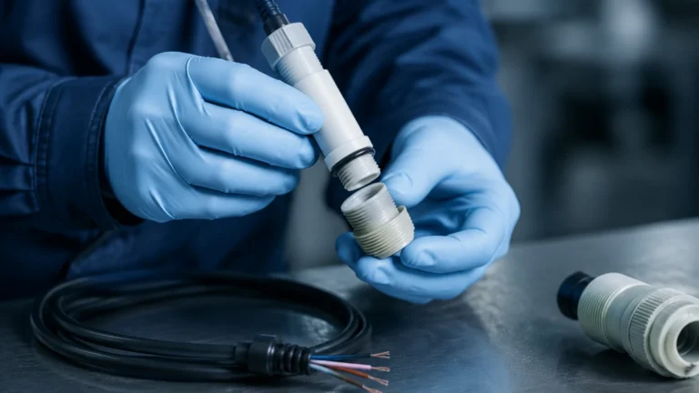
The transmitter provides the excitation current to the coils and amplifies the low-voltage signal from the electrodes. Modern transmitters offer digital displays, 4-20mA outputs, pulse outputs, and communication protocols such as Modbus or HART. For complex systems, users can Review product options and application support on the Welk Main Page to find compatible transmitter configurations.
Selection Criteria: Liners and Electrodes
Choosing the correct materials for the liner and electrodes is the most critical step in specifying an electromagnetic flowmeter. Incorrect material selection can lead to chemical degradation, leaks, or signal interference.
Liner Material Selection
* PTFE (Polytetrafluoroethylene): Excellent chemical resistance and high-temperature tolerance. Ideal for strong acids and bases. However, it is susceptible to mechanical wear from abrasive slurries.
* PFA (Perfluoroalkoxy): Similar to PTFE but with better mechanical stability at high temperatures and better resistance to vacuum conditions.
* Neoprene/Chloroprene Rubber: Highly resistant to wear and abrasion. Frequently used in water treatment and for fluids containing small solids.
* Polyurethane: Exceptional abrasion resistance, making it the standard choice for mining slurries and sand-laden water.
Electrode Material Selection
* Stainless Steel 316L: Suitable for water, wastewater, and mildly corrosive liquids.
* Hastelloy C: Used for seawater and various organic/inorganic acids.
* Titanium: Required for chloride-rich environments and specific chemical processes.
* Tantalum: Reserved for highly aggressive media like concentrated hydrochloric or sulfuric acid.
Technical Selection Table
The following table provides a general reference for matching liner and electrode materials to specific industrial applications.
| Application Type | Recommended Liner | Recommended Electrode | Temperature Range (Typical) |
| :— | :— | :— | :— |
| Potable Water / HVAC | Neoprene / Hard Rubber | SS316L | -10°C to +80°C |
| Municipal Wastewater | Neoprene / Polyurethane | SS316L / Hastelloy C | -10°C to +60°C |
| Strong Acids (HCl, H2SO4) | PTFE / PFA | Tantalum / Platinum | -20°C to +150°C |
| Mining Slurries | Polyurethane | Hastelloy C | -10°C to +50°C |
| Food & Beverage | PFA (FDA approved) | SS316L | -20°C to +130°C |
| Chemical Processing | PTFE | Titanium | -20°C to +120°C |
Installation Guidelines for Optimal Performance
To ensure the electromagnetic flowmeter operates within its specified accuracy limits, strict adherence to installation best practices is required. The flow profile must be stable and fully developed before it reaches the sensor.
Straight Pipe Runs
Flow disturbances caused by valves, pumps, or elbows can create turbulence that affects the induced voltage signal. As a standard engineering rule:
* Upstream: Maintain at least 5D (5 times the nominal pipe diameter) of straight pipe before the meter.
* Downstream: Maintain at least 2D of straight pipe after the meter.
Full Pipe Requirement
The electromagnetic flowmeter must always be installed in a section of the pipe that remains 100% full of liquid. If the pipe is only partially full, the meter will provide inaccurate readings or fail to function. For this reason, vertical installations with upward flow are preferred, as they naturally ensure a full pipe.
Grounding
Grounding is perhaps the most overlooked aspect of magmeter installation. Since the induced voltage is often in the millivolt range, any stray electrical noise in the pipeline can interfere with the signal.
* If the pipeline is metal and unlined, the meter can be grounded directly to the pipe flanges.
* If the pipeline is plastic or lined, grounding rings must be installed between the meter and the pipe flanges to provide a reference potential for the fluid.
Orientation
While magmeters can be installed horizontally or vertically, horizontal installations should have the electrodes positioned on the sides (3 and 9 o'clock positions). This prevents air bubbles at the top of the pipe or sediment at the bottom from interfering with the electrode contact.
Limitations and Operating Constraints
While the electromagnetic flowmeter is a robust tool, it is not a "one-size-fits-all" solution. There are specific technical boundaries to its application:
1. Fluid Conductivity: The most significant limitation is that the fluid must be electrically conductive. Most magmeters require a minimum conductivity of 5 μS/cm. This means they cannot measure hydrocarbons (oils), distilled water, or gases.
2. Vacuum Conditions: Some liners, particularly PTFE, can collapse or peel away from the sensor body if subjected to high vacuum. For vacuum applications, PFA liners with mechanical reinforcement are usually required.
3. Velocity Limits: For accurate measurement, fluid velocity should typically fall between 0.3 m/s and 10 m/s. Velocities below 0.3 m/s may result in a signal-to-noise ratio that is too low for reliable data.
4. Temperature and Pressure: The maximum operating limits are dictated by the liner material and the flange rating. High-temperature steam cleaning (CIP) in food applications requires specific PFA liners.
The Role of Flow and Level Measurement in Process Control
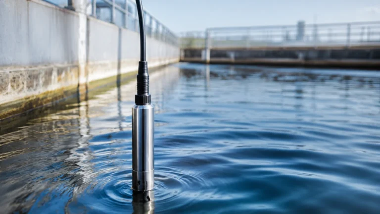
In many industrial automation scenarios, flow measurement and level measurement are used in tandem to provide a complete picture of process efficiency. For example, in a chemical dosing tank, an ultrasonic or radar level sensor monitors the inventory, while an electromagnetic flowmeter measures the precise amount of chemical being discharged into the process.
Welk specializes in both domains, ensuring that level measurement instruments and flow sensors work seamlessly within a single control architecture. By integrating these technologies, plant operators can detect leaks (discrepancies between level drop and flow rate) and optimize pump performance. For a comprehensive look at how these systems integrate, engineers are encouraged to visit the Main Page for detailed technical specifications and cross-product compatibility.
Frequently Asked Questions (FAQ)
Q: Can an electromagnetic flowmeter measure the flow of oil or fuel?
A: No. Petroleum-based products are non-conductive. A magmeter requires a conductive medium (usually water-based) to induce the necessary voltage signal.
Q: What is the maintenance requirement for a magmeter?
A: Because there are no moving parts, maintenance is minimal. However, in applications with coating-prone liquids (like wastewater with high grease content), periodic cleaning of the electrodes may be necessary to prevent signal insulation.
Q: How does air in the line affect the measurement?
A: Air bubbles can cause significant errors because they are non-conductive. If a large slug of air passes through, the meter may read zero or fluctuate wildly. Always install the meter at a low point in the piping system to avoid air entrapment.
Q: Is it possible to use a magmeter for gravity-fed systems?
A: Yes, provided the flow rate is high enough to meet the minimum velocity requirements (typically >0.3 m/s) and the pipe remains completely full.
Q: Do I need to recalibrate the meter if I change the fluid?
A: Generally, no. Since the measurement is based on velocity and the pipe's cross-sectional area, the meter is independent of fluid properties like density and viscosity, as long as the conductivity remains above the threshold.
By carefully considering the liner and electrode compatibility, following precise installation protocols, and understanding the conductivity requirements of the media, the electromagnetic flowmeter provides an exceptionally durable and accurate solution for industrial fluid management. For further technical assistance or to explore specific models, visit the Welk Main Page for professional guidance.