Live Resin Extraction Machine
Live Resin Extraction Machine
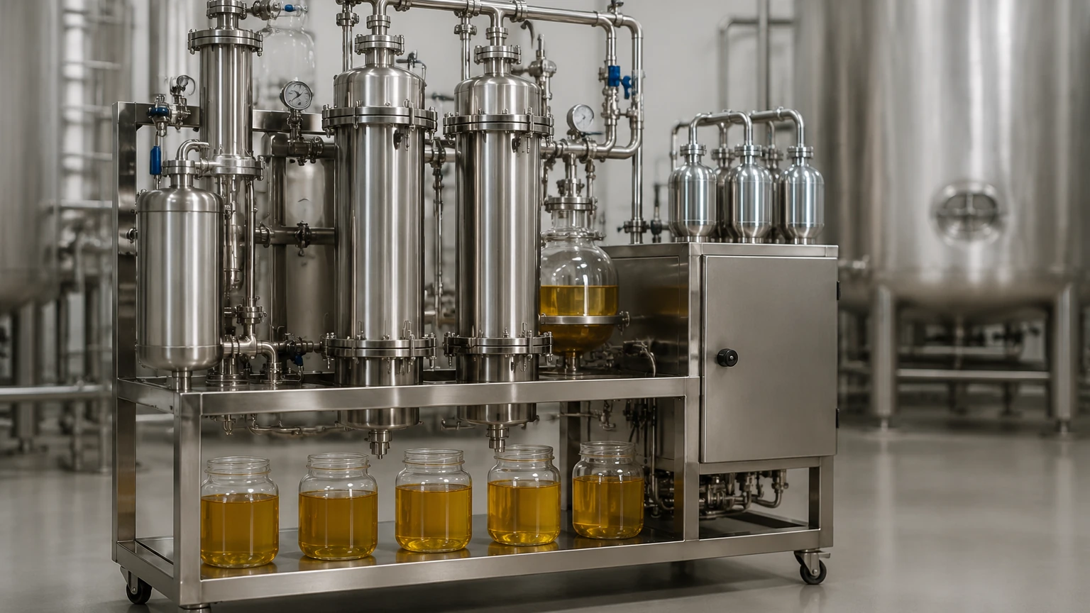
In the specialized field of botanical processing, the live resin extraction machine represents a pinnacle of low-temperature chemical engineering. Unlike standard extraction methods that utilize dried plant material, live resin production requires the processing of "fresh-frozen" biomass. This approach preserves the volatile terpene profiles that are often lost during the curing and drying process. For industrial operators, selecting and maintaining a live resin extraction machine involves a deep understanding of thermodynamics, solvent behavior, and precise process monitoring through advanced instrumentation.
To achieve the high-purity results required in B2B markets, these machines must operate under extreme conditions, often involving cryogenic temperatures and pressurized flammable solvents. This guide explores the technical architecture of these systems, the critical role of level measurement in process automation, and the engineering considerations necessary for safe, efficient operation.
Fundamentals of Live Resin Extraction
Live resin extraction is defined by its ability to capture the full chemical spectrum of the source material. The process begins with biomass that is flash-frozen immediately after harvest, typically using liquid nitrogen or dry ice, to temperatures below -40°C (-40°F). The extraction machine must maintain these sub-zero temperatures throughout the primary solvent contact phase to prevent the co-extraction of unwanted lipids and waxes.
The Role of Solvents
Most industrial-scale live resin extraction machines utilize hydrocarbons, specifically light petroleum gases like butane, propane, or a blend of both. These solvents have low boiling points, allowing them to be purged from the final extract at temperatures that do not degrade the sensitive terpenes. Because these solvents are highly flammable and operate under pressure, the extraction machine is designed as a "Closed-Loop System" (CLS). In a CLS, the solvent is recovered and recycled within the machine, minimizing environmental exposure and operational costs.
Components of an Industrial Live Resin Extraction Machine
An industrial-grade extraction system is composed of several high-pressure vessels, heat exchangers, and a complex network of piping. Each component must be rated for the specific pressures and temperatures encountered during the cycle.
1. Solvent Reservoir: The storage tank for the liquid hydrocarbon. This vessel requires precise level monitoring to ensure there is sufficient solvent for the batch and to prevent overfilling during the recovery phase.
2. Material Columns: These jacketed stainless steel tubes hold the frozen biomass. The solvent passes through these columns to dissolve the target compounds.
3. Collection Vessel: This is where the solvent-extract mixture (often called "miscella") is gathered. Heat is applied here to begin the evaporation of the solvent.
4. Recovery Pump and Condenser: These components pull the solvent vapor from the collection vessel, compress it, and cool it back into a liquid state for return to the reservoir.
Level Measurement Principles in Extraction Systems
In a live resin extraction machine, accurate level measurement is not merely a matter of inventory; it is a critical safety and process control requirement. Understanding the physics behind these measurements is essential before selecting instrumentation for a system.
Radar Level Measurement (Non-Contact)
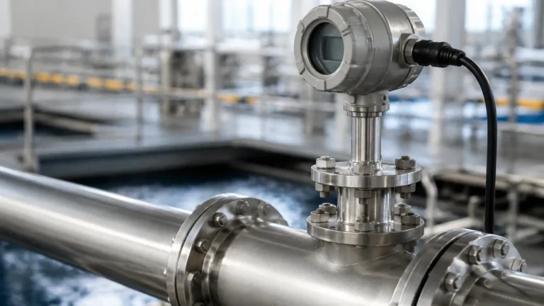
Radar level transmitters, particularly Frequency Modulated Continuous Wave (FMCW) radar, are increasingly common in solvent reservoirs. The device emits a high-frequency signal that reflects off the surface of the liquid. By measuring the time-of-flight or the frequency shift, the sensor calculates the distance to the product.
* Principle: Radar signals are unaffected by the vacuum or high-pressure vapors present in a closed-loop system. Because the sensor does not touch the liquid, it is ideal for maintaining the high sanitary standards required in botanical processing.
* Application: Used in solvent tanks where the dielectric constant of the hydrocarbon is stable enough to provide a reliable reflection.
Hydrostatic Pressure Measurement
Hydrostatic level sensors measure the pressure exerted by the liquid column at the bottom of a tank. The relationship is defined by the formula: $P = \rho \cdot g \cdot h$, where $P$ is pressure, $\rho$ is the density of the fluid, $g$ is gravity, and $h$ is the height of the liquid.
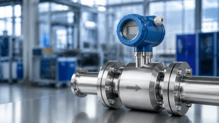
* Principle: In a pressurized extraction vessel, a differential pressure (DP) approach is required. One sensor measures the liquid head pressure at the bottom, while another measures the gas-phase pressure at the top. The system subtracts the top pressure to determine the true liquid level.
* Application: Effective for collection pots where the liquid density is known and relatively constant.
Magnetic Level Gauges
For visual confirmation, magnetic level gauges are often used as a secondary safety measure. A float containing a magnet moves with the liquid level inside a bypass chamber, flipping colored flags on the outside of the tube.
* Principle: This is a mechanical measurement that requires no power, providing a fail-safe visual check for operators even during power outages.
* Application: External mounting on solvent tanks or recovery vessels.
Selecting Level Sensors for Cryogenic and High-Pressure Environments
When outfitting a live resin extraction machine, the instrumentation must meet specific B2B industrial standards. Standard water-grade sensors will fail in the presence of hydrocarbons or cryogenic temperatures.
| Criteria | Requirement for Extraction Machines | Recommended Technology |
| :— | :— | :— |
| Temperature Range | -60°C to +80°C (-76°F to 176°F) | Radar or Specialized Hydrostatic |
| Pressure Rating | Up to 10 bar (150 PSI) or higher | High-pressure Radar / DP Transmitters |
| Safety Rating | Class I, Div 1 / ATEX Zone 0/1 | Explosion-proof (Ex d) or Intrinsically Safe (Ex i) |
| Material | 316L Stainless Steel / PTFE | All contact parts must be solvent-resistant |
| Accuracy | ±2mm to ±5mm | Guided Wave Radar or FMCW Radar |
For engineers looking to integrate these components into a larger automation framework, reviewing the Main Page of specialized instrument manufacturers like Welk provides the necessary technical data sheets and certification documentation required for compliance.
Installation and Maintenance Guidelines
Proper installation is paramount to ensure the longevity of the extraction machine's sensors and the safety of the facility.
Mounting Considerations
* Avoid Turbulence: In the collection vessel, the boiling of solvent can create foam and turbulence. Level sensors should be mounted in a stilling well or away from the heat source to ensure a stable surface for measurement.
* Nozzle Length: For radar sensors, the mounting nozzle should be kept short to prevent signal interference from the nozzle walls (the "ringing" effect).
* Seal Integrity: Given the use of pressurized hydrocarbons, all sensor entries must use high-quality gaskets (typically PTFE or Viton, depending on solvent compatibility) and be leak-tested under pressure.
Calibration in Cold Environments
Density-based measurements (like hydrostatic pressure) must account for the fact that hydrocarbons become more dense at cryogenic temperatures. If a sensor is calibrated at room temperature, it may provide inaccurate readings when the machine is at its operating temperature of -40°C. Modern digital transmitters allow for temperature compensation to be programmed directly into the device logic.
Safety and Limitations
While a live resin extraction machine is designed for efficiency, it has inherent limitations and risks:
1. Vapor Density: Hydrocarbon vapors are heavier than air. Level sensors must be part of a larger safety interlock system that includes gas detection and emergency shut-off valves.
2. Dielectric Constant: Some solvents have a very low dielectric constant ($ε_r < 2.0$), which can make them difficult for standard radar to detect. In these cases, Guided Wave Radar (GWR), which uses a physical probe to guide the signal, is the preferred solution.
3. Cleaning (CIP): Extraction machines require frequent cleaning to prevent cross-contamination between batches. Sensors should be rated for Clean-In-Place (CIP) procedures, meaning they can withstand high-pressure sprays and cleaning agents without needing removal.
Frequently Asked Questions (FAQ)
Q: Why can't I use ultrasonic sensors in a live resin extraction machine?
A: Ultrasonic sensors rely on sound waves traveling through the air. In a closed-loop hydrocarbon system, the vapor composition and pressure changes significantly alter the speed of sound, leading to massive measurement errors. Additionally, many ultrasonic sensors are not rated for the hazardous (Class I, Div 1) environments typical of these machines.
Q: How often should level sensors be calibrated?
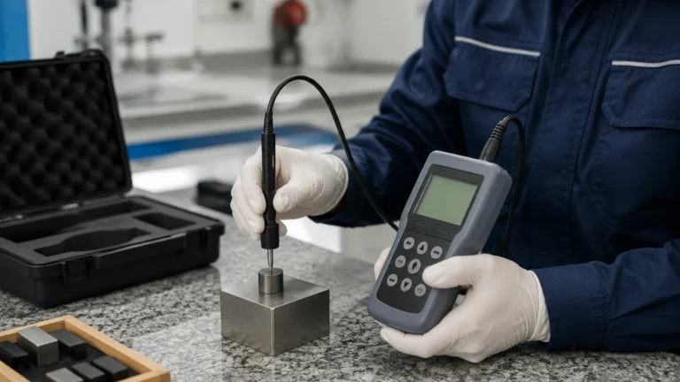
A: For industrial B2B operations, an annual calibration is standard. However, in high-throughput extraction facilities, a quarterly verification against a manual gauge or sight glass is recommended to ensure drift has not occurred due to extreme thermal cycling.
Q: Can one sensor handle both the extraction and the cleaning phases?
A: Yes, provided the sensor is made of 316L stainless steel and has a wide enough temperature and pressure range. Radar sensors are particularly good at this because they are non-contact and do not have diaphragms that can be damaged by aggressive cleaning chemicals.
Conclusion
The efficiency of a live resin extraction machine is directly tied to the precision of its sub-systems. By implementing robust level measurement technologies, operators can ensure consistent batch quality, maximize solvent recovery, and maintain a safe working environment. For further technical specifications on level measurement for industrial automation, visit the Welk Main Page to explore product options tailored for hazardous and cryogenic applications.