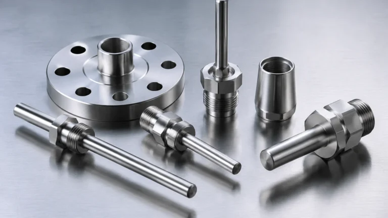
Fdu90
Fdu90
In the landscape of industrial automation and process control, non-contact level measurement has become a cornerstone for ensuring operational efficiency and safety. Among the various technologies available, ultrasonic transducers like the fdu90 represent a standard for reliable, cost-effective measurement in both liquid and solid applications. This guide provides a detailed technical overview of the fdu90 sensor, its underlying measurement principles, selection criteria, and practical installation considerations for engineering professionals.
Understanding the Ultrasonic Measurement Principle
Before evaluating specific hardware like the fdu90, it is essential to understand the physics of ultrasonic level detection. This technology relies on the "Time-of-Flight" (ToF) principle. The transducer acts as both a transmitter and a receiver.
1. Emission: The piezoelectric crystal within the fdu90 converts electrical energy into mechanical vibrations, emitting a series of ultrasonic pulses.
2. Propagation: These sound waves travel through the medium (usually air) toward the surface of the material being measured.
3. Reflection: Upon hitting the surface—whether it is water, chemical sludge, or bulk solids—the waves are reflected back toward the sensor.
4. Detection: The sensor detects the returning echo. The associated electronic transmitter (such as the FMU90 series) calculates the distance based on the time elapsed between emission and reception.
The formula used is:
Distance = (Speed of Sound × Time) / 2
Because the speed of sound is influenced by air temperature, high-quality sensors like the fdu90 often incorporate an integrated temperature sensor to provide real-time compensation, ensuring accuracy even as environmental conditions fluctuate.
Technical Specifications and Capabilities of the Fdu90
The fdu90 is designed as a rugged, high-performance transducer for continuous, non-contact level measurement. It is particularly noted for its ability to handle demanding environmental conditions while maintaining a narrow beam angle.
Measurement Range
* Liquids: Typically up to 23 meters (approx. 75 feet).
* Bulk Solids: Typically up to 12 meters (approx. 39 feet).
The effective range is influenced by the reflective properties of the material. Smooth liquid surfaces reflect sound waves more efficiently than porous or uneven solid surfaces, which tend to scatter the signal.
Frequency and Beam Angle
The fdu90 operates at a frequency of approximately 40 kHz. One of its primary engineering advantages is its narrow beam angle, usually around 11°. A narrow beam is critical in industrial silos or tanks with internal obstructions (such as ladders, heating coils, or agitators), as it minimizes the risk of false echoes from these structures.
Material Construction and Durability
To suit diverse industrial environments, the sensor is often constructed from chemically resistant materials:
* Housing: Typically PVDF (Polyvinylidene fluoride) or 316L stainless steel.
* Protection Rating: Often rated at IP68 (NEMA 6P), making it suitable for applications where the sensor might be temporarily submerged or exposed to heavy moisture.
Industrial Application Scenarios
The versatility of the fdu90 makes it a preferred choice across several sectors. Engineering teams typically specify this transducer for the following applications:
1. Water and Wastewater Treatment
In municipal water management, the fdu90 is frequently used for level measurement in basins, pump stations, and storage tanks. Furthermore, when paired with a sophisticated transmitter, it is used for flow measurement in open channels (flumes and weirs) by converting the measured level into a flow rate based on standardized hydraulic formulas.
2. Bulk Solids Monitoring
For small to medium-sized silos containing plastic pellets, grains, or crushed stone, the fdu90 provides a reliable inventory management solution. Its ability to ignore minor dust concentrations makes it more robust than certain optical sensors, though extreme dust may still require radar-based alternatives.
3. Chemical Processing
Due to the non-contact nature of the measurement, the fdu90 is ideal for corrosive liquids. Since the sensor never touches the medium, there is no risk of chemical corrosion of the internal components, provided the housing material (PVDF) is compatible with the tank's vapors.
Selection Criteria: Fdu90 vs. Alternative Transducers
Choosing the right transducer requires a balance between range, frequency, and environmental constraints. The following table compares the fdu90 with other common models in the same family to assist in the selection process:
| Feature | FDU90 | FDU91 | FDU92 |
| :— | :— | :— | :— |
| Max Range (Liquids) | 23m (75ft) | 10m (33ft) | 20m (65ft) |
| Max Range (Solids) | 12m (39ft) | 5m (16ft) | 10m (33ft) |
| Blocking Distance | 0.4m (1.3ft) | 0.3m (1.0ft) | 0.4m (1.3ft) |
| Frequency | 40 kHz | 43 kHz | 30 kHz |
| Primary Use | Deep tanks/Silos | Small vessels | Medium vessels |
When selecting a sensor, engineers must prioritize the Blocking Distance (also known as the Dead Zone). This is the area directly in front of the sensor face where measurements are not possible. For the fdu90, any material rising within 0.4 meters of the sensor will result in an error or inaccurate reading.

Installation and Engineering Best Practices
Proper installation is the most significant factor in the long-term reliability of an ultrasonic system. Even the most advanced sensor will fail if placed incorrectly.
Orientation and Positioning
* Perpendicularity: The sensor face must be mounted perfectly parallel to the product surface. If the sensor is tilted, the ultrasonic pulse may reflect away from the transducer rather than back to it, resulting in a "Loss of Echo" (LOE) error.
* Avoid the Center: In cylindrical tanks, do not mount the sensor in the exact center, as this can lead to multiple reflections that interfere with the primary signal. Ideally, mount the sensor at a distance of 1/6th of the tank diameter from the wall.
* Internal Obstructions: Ensure the signal path is clear of fill streams, ladders, and limit switches. If an obstruction is unavoidable, many modern transmitters allow for "Fixed Target Suppression" to digitally map out and ignore these static echoes.
Mounting Options
The fdu90 typically features a G 1½" or 1½" NPT thread for easy installation. It can be mounted on a nozzle, a ceiling bracket, or a cantilever arm over open channels. When mounting on a nozzle, the nozzle height must be kept as short as possible to prevent the ultrasonic pulse from reflecting off the nozzle walls before it even enters the tank.
Limitations and Environmental Considerations
While the fdu90 is highly capable, ultrasonic technology has inherent physical limits that engineers must account for during the design phase:
1. Vacuum Applications: Sound requires a medium to travel. Therefore, ultrasonic sensors cannot function in a vacuum.
2. Heavy Foam: Thick, dense foam on a liquid surface can absorb the ultrasonic pulse rather than reflecting it. In these cases, hydrostatic pressure or guided wave radar may be more appropriate.
3. Temperature Gradients: While the fdu90 compensates for temperature at the sensor head, significant temperature variations throughout the tank (e.g., a very hot liquid with cold air above it) can cause minor inaccuracies in the ToF calculation.
4. High Pressure: Ultrasonic sensors are generally limited to atmospheric or near-atmospheric pressure (typically up to 3 bar or 43 psi). High pressure changes the density of the air, which significantly alters the speed of sound.
Maintenance and Troubleshooting
The fdu90 is virtually maintenance-free because it has no moving parts. However, in specific applications, the following checks should be performed annually:
* Sensor Face Cleaning: In wastewater or high-humidity environments, condensation or biological growth may accumulate on the transducer face. Wiping the face with a soft cloth and mild detergent is usually sufficient.
* Cable Integrity: Ensure the cable gland is tight and there is no moisture ingress into the connection compartment. For long cable runs, ensure the shielding is properly grounded to prevent electromagnetic interference (EMI).
* Diagnostic Echo Curves: Use the connected transmitter to view the "Envelope Curve." This visual representation of the echoes allows technicians to see the strength of the reflection and identify potential interference before it causes a system failure.
Conclusion
The fdu90 remains a vital tool for industrial level measurement, offering a blend of range and precision that satisfies the requirements of most standard tank and silo applications. By understanding the acoustic principles and adhering to strict installation guidelines, process engineers can implement a measurement solution that provides years of reliable data. For those seeking to explore a wider range of measurement technologies—including radar, hydrostatic, and magnetic solutions—it is helpful to Review product options and application support on our Main Page to ensure the selected instrument aligns perfectly with specific process demands.
***
Frequently Asked Questions (FAQ)
Q: Can the fdu90 be used in explosive atmospheres?
A: Yes, the fdu90 is typically available with various international explosion-proof certifications (such as ATEX, FM, or CSA), provided it is installed with the appropriate intrinsic safety barriers or explosion-proof housing as specified by local codes.
Q: What is the maximum cable length between the fdu90 and the transmitter?
A: Depending on the cable type and environmental interference, the distance can typically reach up to 300 meters (approx. 980 feet). It is recommended to use the manufacturer's specified shielded twisted-pair cable to maintain signal integrity.
Q: How does wind affect the fdu90 in outdoor applications?
A: Strong wind can "blow" the ultrasonic pulse away, especially over long distances. For outdoor open-channel flow measurement, using a weather shield or mounting the sensor closer to the liquid surface can mitigate this effect.