Incilator
Incilator
In the field of industrial process control, the ability to monitor liquid levels accurately and reliably is a fundamental requirement. An incilator, or level indicator, serves as the primary visual or electronic interface between a storage vessel and the operator. Whether used for inventory management, process safety, or operational efficiency, choosing the correct incilator technology is critical for maintaining plant integrity. This guide explores the principles of level indication, the various technologies available, and the practical considerations for selecting and installing these instruments in demanding environments.
Principles of Level Indication and Measurement
Before selecting an incilator, it is essential to understand the physical principles that govern level measurement. Industrial level indicators generally fall into two categories: direct-reading indicators and indirect-reading indicators.
Buoyancy and Magnetism
Many mechanical incilators, such as Magnetic Level Indicators (MLI), operate on the principle of buoyancy. A float, specifically engineered to be lighter than the process fluid, moves up and down a bypass chamber as the liquid level changes. Inside this float is a high-intensity magnetic assembly. This magnet interacts with a series of bi-color flaps or a follower on the outside of the chamber. As the float moves, the magnetic field flips the flaps to a different color (usually red for liquid and white for gas), providing a clear, high-visibility representation of the level without the need for glass in contact with the process.
Light Refraction and Reflection
Traditional glass gauges rely on the optical properties of the liquid. In a reflex glass incilator, the inner surface of the glass has prismatic grooves. When light hits the glass in the vapor space, it is reflected back to the observer, appearing bright. When light hits the glass in the liquid space, the liquid fills the grooves, and the light is refracted into the fluid, making the liquid column appear dark. This contrast allows for immediate manual readings.
Electronic Sensing
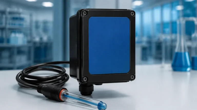
Modern industrial systems often supplement visual incilators with electronic sensors. These may use hydrostatic pressure, where the weight of the liquid column is measured, or time-of-flight technologies like radar and ultrasonic waves. These electronic signals are then transmitted to a digital incilator or control system for remote monitoring and data logging. For a comprehensive overview of these advanced sensing technologies, engineers often consult a Main Page of specialized instrument manufacturers to compare performance metrics.
Types of Incilator Technologies
Selecting the right incilator requires an understanding of the specific strengths and weaknesses of each technology type.
1. Magnetic Level Indicators (MLI)
Magnetic indicators are the preferred choice for high-pressure, high-temperature, or toxic applications where glass breakage would pose a significant safety risk.
- Advantages: No glass in contact with the process; high visibility from a distance; virtually maintenance-free.
- Limitations: Not suitable for liquids with high magnetic particles or extremely high viscosity that might impede float movement.
2. Reflex and Transparent Glass Gauges
These are the traditional "sight glasses" used in many boiler and tank applications.
- Reflex Gauges: Best for clean, colorless liquids where a sharp contrast is needed.
- Transparent Gauges: Used when the color or interface of two different liquids needs to be observed, or when the liquid is highly corrosive to glass (requiring mica shields).
3. Hydrostatic Level Transmitters
These devices measure the pressure at the bottom of a tank and convert it into a level reading based on the fluid's density. They are often paired with a digital incilator display.
- Advantages: Easy to install; no moving parts in the tank.
- Limitations: Accuracy is dependent on constant fluid density.
4. Radar and Ultrasonic Level Meters
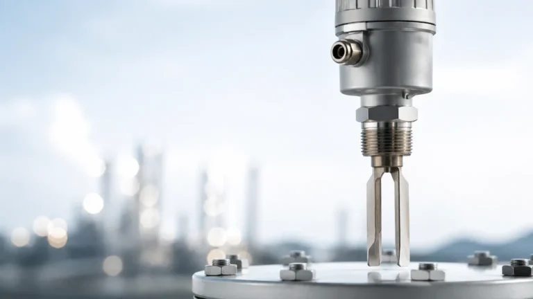
Non-contact methods that are ideal for corrosive or sticky substances. They transmit a signal that reflects off the liquid surface and returns to the sensor.
- Advantages: Extremely accurate; works with solids and liquids.
- Limitations: Can be affected by heavy foam or internal tank obstructions.
Practical Selection Table
When evaluating an incilator for a specific project, use the following table as a baseline for comparison:
| Feature | Magnetic Level Indicator | Reflex Glass Gauge | Radar Level Meter | Hydrostatic Transmitter |
| :— | :— | :— | :— | :— |
| Max Pressure | Up to 350 bar (5076 psi) | Up to 250 bar (3625 psi) | N/A (Non-contact) | Up to 400 bar (5800 psi) |
| Max Temp | Up to 540°C (1004°F) | Up to 400°C (752°F) | Up to 450°C (842°F) | Up to 120°C (248°F) |
| Visibility | Excellent (Flags) | Good (Contrast) | Digital Display | Digital Display |
| Maintenance | Low | Moderate (Cleaning) | Very Low | Moderate |
| Media Type | Clean Liquids | Clean Liquids | Liquids/Solids | Clean Liquids |
Installation Considerations for Incilators
The reliability of an incilator is heavily dependent on correct installation. Even the most advanced instrument will fail if the physical environment is not properly prepared.
1. Nozzle Alignment and Sizing
For bypass-style incilators, the vessel nozzles must be perfectly aligned. Misalignment can cause the chamber to tilt, leading to friction between the float and the chamber wall. This friction can cause the float to "stick," providing false readings. It is recommended that nozzles have a minimum diameter of 25 mm (1 inch) to allow for sufficient flow and to prevent clogging.
2. Venting and Draining
Every incilator installation should include vent and drain valves. The vent valve at the top allows for the removal of trapped air or gas during startup, while the drain valve at the bottom is essential for cleaning the chamber and removing sediment. In applications with hazardous chemicals, these vents and drains should be piped back to a recovery system or a flare header.
3. Insulation and Heat Tracing
In cold climates or for processes involving high-viscosity liquids (like heavy crude or bitumen), the incilator may require insulation or steam/electric heat tracing. If the liquid in the chamber cools down and thickens, the float may not move accurately. However, when using magnetic incilators, ensure that the insulation does not interfere with the magnetic coupling between the float and the external scale.
4. Avoiding Magnetic Interference
Since magnetic incilators rely on sensitive magnetic fields, they should be installed away from large ferrous structures or high-voltage power lines that could create electromagnetic interference. Standard practice suggests a minimum clearance of 100 mm (4 inches) from any carbon steel supports or brackets.

Limitations and Common Risks
While incilators are robust, they are not universal solutions. Engineers must be aware of specific risks:
* Flash Vaporization: In high-temperature applications, if the pressure in the incilator chamber drops suddenly, the liquid may "flash" into vapor. This can cause the float to bounce violently, potentially damaging the internal magnetic assembly.
* Coating and Scaling: If the process fluid is prone to leaving deposits, the internal walls of the chamber or the glass surface can become coated. This obscures visibility or prevents the float from moving. Regular flushing is required in these scenarios.
* Specific Gravity Fluctuations: Mechanical incilators are calibrated for a specific fluid density (Specific Gravity). If the process fluid changes significantly (e.g., switching from water to an oil-based solvent), the float may sink or sit too high in the liquid, leading to inaccurate readings.
* Vibration: Excessive mechanical vibration in the piping system can cause the indicating flags of a magnetic incilator to flip erroneously. In such cases, dampening mounts or "vibration-proof" flag designs should be specified.
Confirming Project Requirements
Before finalizing a purchase or installation plan, the project team should confirm the following data points:
1. Fluid Properties: What is the chemical composition, density, and viscosity at operating temperature?
2. Operating Limits: What are the maximum and minimum design pressures and temperatures?
3. Material Compatibility: Are the wetted parts (316L Stainless Steel, Hastelloy, PVC, etc.) compatible with the process media?
4. Certification Needs: Does the site require PED (Pressure Equipment Directive), ATEX (Explosion Proof), or ASME certification?
For detailed technical specifications and to explore various model options tailored to specific industrial needs, reviewing the resources available on the manufacturer's Main Page is highly recommended.
Frequently Asked Questions (FAQs)
Q: Can an incilator be used for interface measurement between two liquids?
A: Yes, specifically designed magnetic incilators can use a float weighted to sink through the upper liquid (e.g., oil) but float on the lower liquid (e.g., water). This allows for clear indication of the interface level.
Q: How often should a glass-based incilator be inspected?
A: In high-pressure steam applications, glass should be inspected every 6 to 12 months for signs of thinning or "frosting" caused by chemical attack. In non-corrosive, ambient conditions, annual inspections are usually sufficient.
Q: What is the maximum length for a bypass incilator?
A: While standard sections are often up to 6 meters (approx. 20 feet), incilators can be manufactured in multiple sections to cover much larger heights. However, for very tall tanks, electronic non-contact methods like radar are often more cost-effective.
Q: Do magnetic incilators require power?
A: The basic visual indication (the flipping flags) is entirely mechanical and requires no power. However, if you add a transmitter or limit switches for remote monitoring, those components will require a standard 24V DC power supply.
By understanding these technical nuances, plant engineers can ensure that their level monitoring systems provide the safety and accuracy required for modern industrial operations.