Fill Level Monitoring
Fill Level Monitoring
Fill level monitoring is a fundamental requirement in modern industrial processes, serving as the primary mechanism for inventory control, process safety, and automation efficiency. Whether managing bulk solids in a cement silo or corrosive chemicals in a storage tank, the ability to accurately determine the volume of material within a vessel is critical to preventing overfills, ensuring continuous supply, and optimizing production cycles. This guide examines the engineering principles, technology selection, and practical installation requirements for effective fill level monitoring across various industrial sectors.
Core Measurement Principles
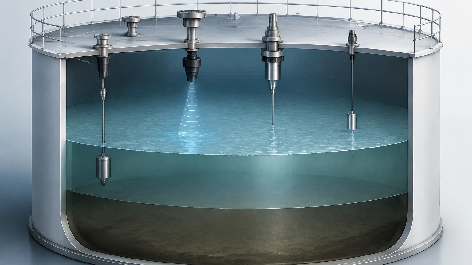
To select the appropriate instrumentation, it is essential to understand the physical principles that govern level measurement. Modern fill level monitoring technologies are generally categorized into non-contact and contact methods, each utilizing different physical properties of the media and the environment.
Time-of-Flight (ToF)
Time-of-Flight is the principle used by radar and ultrasonic sensors. The device emits a signal (either an electromagnetic wave or a sound wave) that travels to the surface of the material, reflects, and returns to the sensor. By measuring the time interval between emission and reception, the distance to the product surface is calculated.
Hydrostatic Pressure
This principle relies on the relationship between the height of a liquid column and the pressure it exerts at the base of the vessel. In a vented tank, the pressure ($P$) is equal to the density of the liquid ($
ho$) multiplied by gravity ($g$) and the height of the liquid ($h$). This method is highly reliable for liquids with a constant density.
Buoyancy and Magnetic Coupling
Mechanical level measurement often utilizes buoyancy. A float moves with the liquid level, and its position is transmitted either through a mechanical linkage or, more commonly in modern industrial settings, via magnetic coupling to an external indicator or transmitter. This provides a physical, visual representation of the level alongside electronic data.
Technologies for Fill Level Monitoring
Choosing the right technology requires a match between the sensor's capabilities and the specific characteristics of the application, such as temperature, pressure, and the physical state of the media.
Radar Level Meters
Radar level meters are the gold standard for high-accuracy fill level monitoring. They utilize high-frequency microwave pulses (often 26GHz or 80GHz). Because electromagnetic waves do not require a medium for travel and are largely unaffected by air temperature or pressure changes, radar is suitable for vacuum conditions and high-temperature reactors.
* Advantages: Non-contact, high precision (up to ±1mm), and capable of measuring through steam, dust, and vapor.
* Limitations: The dielectric constant (DK) of the material must be sufficient to reflect the signal. Materials with very low DK values may require guided wave radar (GWR).
Ultrasonic Level Sensors
Ultrasonic sensors are widely used in water treatment and simple chemical storage. They emit acoustic pulses that reflect off the surface of the liquid or solid.
* Advantages: Cost-effective, non-contact, and easy to install.
* Limitations: Accuracy is affected by air temperature, turbulence, and heavy foam. They cannot be used in vacuums or high-pressure environments because sound waves require a medium (air) to propagate.
Hydrostatic Level Transmitters
For deep wells, open tanks, or underground reservoirs, hydrostatic transmitters offer a robust solution. These are typically submersible sensors or flange-mounted pressure transmitters.
* Advantages: Simple electronics, high reliability in clean liquids, and unaffected by surface foam.
* Limitations: Errors occur if the density of the liquid changes significantly due to temperature fluctuations or mixing.
Magnetic Level Gauges
Magnetic level gauges are preferred when visual local indication is required for safety or redundant monitoring. They consist of a bypass chamber connected to the vessel, with a float that triggers a series of magnetic flaps or a transmitter.
* Advantages: No power required for visual indication, high pressure/temperature ratings, and clear visibility from a distance.
* Limitations: Not suitable for highly viscous liquids that might cause the float to stick.
Selection Criteria for Industrial Applications
Selecting a fill level monitoring system involves evaluating the process environment against the technical specifications of the instrument. The following table provides a comparative overview of common technologies.
| Technology | Typical Accuracy | Max Range | Media Type | Key Advantage |
| :— | :— | :— | :— | :— |
| Radar (80GHz) | ±1 mm to ±3 mm | 120 m | Liquids / Solids | High precision, ignores dust/vapor |
| Ultrasonic | ±0.25% of range | 15 m to 30 m | Liquids / Slurries | Cost-effective for water/waste |
| Hydrostatic | ±0.1% to ±0.5% | 200 m (H2O) | Liquids Only | Reliable in vented tanks |
| Magnetic Gauge | ±5 mm to ±10 mm | 6 m (standard) | Liquids | Visual local indication |
| Level Switch | N/A (Point) | N/A | Liquids / Solids | Overfill prevention/dry run |
When evaluating these options, engineers should prioritize the Main Page of the manufacturer's technical documentation to verify chemical compatibility and pressure ratings for specific models.
Installation Considerations and Best Practices
Correct installation is as important as technology selection. Even the most advanced radar meter will fail to provide accurate fill level monitoring if installed incorrectly.
1. Dead Zones (Blocking Distance): Every non-contact sensor has a "dead zone" near the sensor face where measurement is impossible. Ensure the maximum fill level of the tank does not enter this zone.
2. Nozzle Geometry: For radar and ultrasonic sensors, the mounting nozzle should be short and wide enough to prevent the signal from reflecting off the nozzle walls rather than the product surface.
3. Obstruction Avoidance: Avoid installing sensors directly above agitators, heating coils, or ladders. These internal structures create "false echoes" that can interfere with the true level signal.
4. Positioning: Sensors should generally be mounted at 1/3 of the tank radius from the wall to avoid wall interference while still obtaining a representative surface reading. Avoid mounting the sensor in the exact center of a domed-roof tank, as this can focus parasitic reflections.
5. Environmental Protection: For outdoor installations, sunshields are recommended to prevent temperature-induced errors in ultrasonic sensors and to protect electronic housings from UV degradation.
Common Risks and Limitations
While modern fill level monitoring systems are highly advanced, certain process conditions present ongoing challenges:
* Foam and Turbulence: Heavy, dense foam can absorb ultrasonic and radar signals, leading to a "loss of echo." In these cases, hydrostatic or guided wave radar is often a better choice.
* Material Build-up: In sticky or viscous applications, material can accumulate on the sensor face or the probe. While some radar sensors feature "mapping" to ignore build-up, extreme cases may require manual cleaning or the use of a non-contact sensor with a flush-mounted antenna.
* Dielectric Variations: If using radar to monitor the fill level of a material whose dielectric constant changes (e.g., a mixture of oil and water), the signal strength may fluctuate, requiring recalibration or the use of a technology independent of DK, such as hydrostatic pressure.
Frequently Asked Questions (FAQ)
Q: Can I use one sensor for both liquid and solid fill level monitoring?
A: Generally, yes, if using radar. However, the internal software must be configured differently. Solids typically have an uneven surface (angle of repose) and lower reflectivity than liquids, requiring more sensitive signal processing.
Q: How often do fill level monitoring sensors need calibration?
A: This depends on the technology. Radar and ultrasonic sensors are solid-state and rarely drift, often requiring only a functional check every 12–24 months. Hydrostatic sensors may need more frequent calibration if the liquid density is not constant.
Q: What is the difference between continuous level measurement and point level detection?
A: Continuous fill level monitoring tracks the level across the entire range (e.g., 0–100%). Point level detection (using level switches) only indicates when a specific level has been reached, such as a high-level alarm for overfill prevention.
Conclusion
Effective fill level monitoring is the result of matching the physical properties of the process media with the appropriate measurement principle. By understanding the strengths and limitations of radar, ultrasonic, hydrostatic, and magnetic technologies, engineers can implement solutions that enhance safety and operational efficiency. For those looking to integrate these systems into a broader automation framework, it is vital to consult detailed product specifications and application guides to ensure long-term reliability in the field.