Liquid Flow Gauge
Liquid Flow Gauge
In industrial process control, the accurate measurement of fluid movement is as critical as monitoring the volume stored within a vessel. A liquid flow gauge is a specialized instrument designed to quantify the flow rate or total volume of a liquid passing through a closed pipe or an open channel. For engineers and facility managers, selecting the correct liquid flow gauge is a balance between fluid characteristics, installation constraints, and required precision.
While level measurement focuses on the vertical position of a liquid surface—often using technologies like radar or ultrasonic sensors provided by manufacturers like Welk—flow measurement monitors the dynamic movement of that liquid over time. Understanding the synergy between these two measurements is vital for comprehensive inventory management and process optimization. To explore how these technologies integrate, you can Review product options and application support on the Welk Main Page.
Understanding Liquid Flow Measurement Principles
Before selecting a liquid flow gauge, it is essential to understand the physical principles that govern different measurement technologies. Most industrial flow meters operate based on one of the following four principles:
1. Velocity-Based Measurement
These gauges calculate flow by measuring the speed of the liquid moving through a known cross-sectional area. The formula $Q = A \times v$ (where $Q$ is flow rate, $A$ is area, and $v$ is velocity) is the foundation for electromagnetic and ultrasonic flow meters.
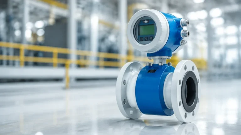
* Electromagnetic (Magmeters): These operate on Faraday’s Law of Induction. When a conductive liquid moves through a magnetic field generated by the meter, it creates a voltage proportional to its velocity. This method is highly accurate and has no moving parts, making it ideal for wastewater and chemical slurries.
* Ultrasonic: These use sound waves to determine velocity. Transit-time ultrasonic meters measure the time difference between signals sent upstream and downstream. Doppler ultrasonic meters measure the frequency shift caused by sound reflecting off particles or bubbles in the liquid.
2. Differential Pressure (DP)
DP flow gauges are among the most common in traditional industrial settings. They work by placing a restriction (like an orifice plate or Venturi tube) in the pipe to create a pressure drop. According to Bernoulli’s equation, the square root of the pressure difference between the upstream and downstream sides is proportional to the flow rate.
3. Mechanical/Positive Displacement
These gauges physically divide the liquid into discrete increments. As the liquid passes through, it moves a mechanical component, such as a turbine, a set of gears, or a rotating disk. Each rotation corresponds to a specific volume. Turbine meters are particularly valued for their high precision in low-viscosity, clean fluids like fuel or treated water.
4. Variable Area (Rotameters)
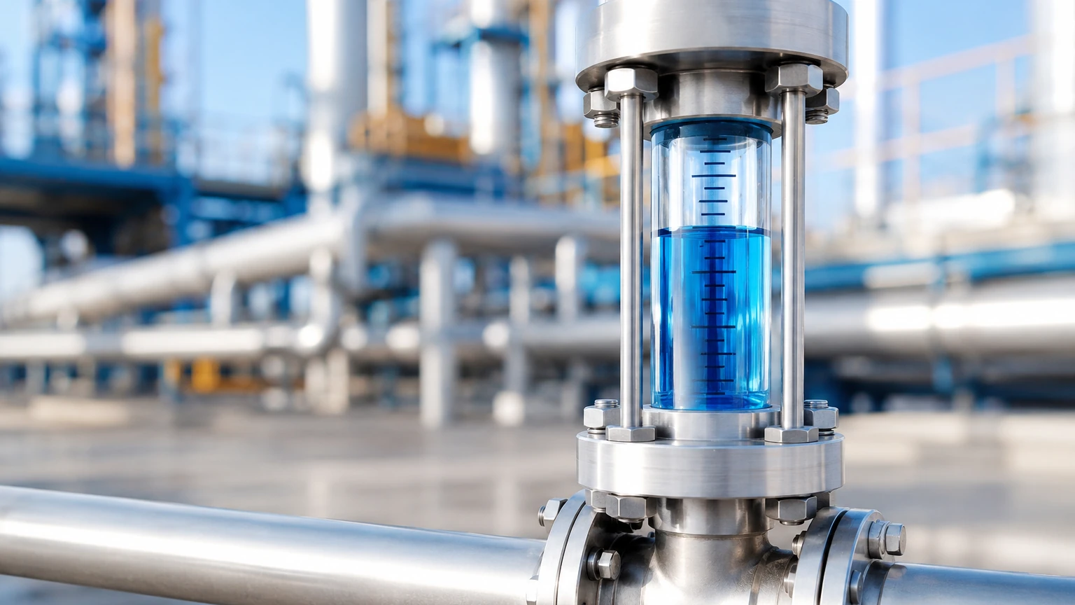
This is a simpler form of a liquid flow gauge consisting of a tapered tube and a float. As the flow increases, the float rises, increasing the area through which the fluid can pass until the upward force of the fluid equals the weight of the float. The position of the float against a scale indicates the flow rate.
Key Types of Liquid Flow Gauges and Their Applications
Selecting the right liquid flow gauge depends heavily on the industry and the specific properties of the fluid being measured.
| Industry | Typical Fluid | Recommended Gauge Type | Reason |
| :— | :— | :— | :— |
| Water Treatment | Raw water, sludge | Electromagnetic | Handles solids, no pressure drop |
| Chemical Processing | Corrosive acids | Ultrasonic (Clamp-on) | No contact with fluid, high safety |
| Oil & Gas | Refined fuels | Turbine | Extremely high accuracy for custody transfer |
| Food & Beverage | Milk, juices | Electromagnetic (Sanitary) | Easy to clean (CIP/SIP compatible) |
| HVAC | Chilled water | Ultrasonic Transit-time | Easy installation on existing pipes |
In many of these applications, flow measurement is paired with level measurement to ensure a complete picture of the system. For instance, in a chemical dosing tank, a liquid flow gauge monitors the output while a radar level meter ensures the supply does not run dry. For more information on integrated measurement solutions, visit the Main Page.
Selection Criteria for Industrial Liquid Flow Gauges
When specifying a liquid flow gauge for a B2B project, engineers must evaluate several technical parameters to avoid premature failure or inaccurate readings.
Fluid Properties
* Conductivity: Electromagnetic meters require a minimum conductivity (usually >5 μS/cm). They will not work with deionized water or hydrocarbons.
* Viscosity: High-viscosity liquids (like heavy oils) can cause significant pressure drops in DP meters and slow down turbine meters.
* Cleanliness: If the liquid contains solids or air bubbles, mechanical meters may clog, and transit-time ultrasonic meters may fail to lock onto a signal.
Process Conditions
* Pressure and Temperature: Ensure the gauge body and seals can withstand the maximum operating pressure (e.g., 40 bar / 580 PSI) and temperature (e.g., 150°C / 302°F).
* Flow Range (Turndown Ratio): This is the ratio between the maximum and minimum flow the meter can accurately measure. A 10:1 turndown ratio means a meter rated for 100 L/min can accurately measure down to 10 L/min.
Accuracy vs. Repeatability
In B2B procurement, it is vital to distinguish between accuracy (how close the reading is to the true value) and repeatability (how consistent the readings are under the same conditions). For dosing applications, repeatability is often more important than absolute accuracy.
Installation Guidelines and Best Practices
Even the most expensive liquid flow gauge will provide inaccurate data if installed incorrectly. Follow these engineering standards for optimal performance:
1. Straight Pipe Runs: Most velocity-based meters require a specific length of straight pipe before (upstream) and after (downstream) the meter to eliminate turbulence. A common rule is "10D upstream and 5D downstream," where D is the pipe diameter. If a 50 mm (2-inch) pipe is used, you need 500 mm of straight pipe before the gauge.
2. Full Pipe Requirement: Most liquid flow gauges are designed to measure liquids in a full pipe. If the pipe is only partially full, the meter will over-read or fail. Installing the meter at a low point in the piping (a "U" trap) ensures it remains flooded.
3. Orientation:
* Vertical Upward: Ideal for most meters as it ensures a full pipe and prevents air pockets.
* Vertical Downward: Generally avoided for liquids as it can lead to partially full pipes.
* Horizontal: Acceptable, but the sensors (electrodes) in a magmeter should be positioned horizontally to avoid interference from air at the top or sediment at the bottom.
4. Grounding: For electromagnetic meters, proper grounding is essential to eliminate electrical noise that can interfere with the small voltage signals generated by the flow.
Common Challenges and Limitations
Every liquid flow gauge has its limitations. Recognizing these early in the design phase prevents costly retrofits.
* Cavitation: If the pressure drops too low inside the meter (common in DP or turbine meters), the liquid may vaporize into bubbles. When these bubbles collapse, they can erode the internal components of the gauge.
* Air Entrainment: Small air bubbles can be read as liquid volume, leading to significant errors. Air eliminators should be installed upstream if the process is prone to aeration.
* Scaling and Coating: In chemical or wastewater applications, material may build up on the internal walls of the gauge. This changes the cross-sectional area ($A$) and leads to drift in accuracy. Non-contact ultrasonic meters or electromagnetic meters with electrode cleaning functions are preferred in these scenarios.
Maintenance and Calibration for Long-term Accuracy
To maintain the integrity of a liquid flow gauge, a scheduled maintenance program is required.
* Zero-Point Check: Periodically check the meter's reading under a "no-flow" condition. The pipe must be full, and the valves must be tightly shut. If the meter shows a flow, a zero-calibration is necessary.
* Verification vs. Calibration: Verification is an in-situ check to ensure the meter’s electronics and sensors are functioning within factory specs. Calibration involves comparing the meter against a traceable reference standard (like a master meter or a weigh scale) and adjusting the output.
* Physical Inspection: For mechanical meters, check for bearing wear or blade damage. For electromagnetic meters, check for liner wear or electrode corrosion.
Frequently Asked Questions (FAQs)
Q: Can a liquid flow gauge measure gas?
A: Generally, no. Most liquid flow gauges (like magmeters) rely on properties specific to liquids. While some technologies like ultrasonic or DP can be adapted for gas, they require different calibrations and sensor configurations.
Q: What is the difference between a flow meter and a flow gauge?
A: In common industrial parlance, they are often used interchangeably. However, a "gauge" sometimes refers to a device that provides a local visual indication (like a rotameter), whereas a "meter" often implies an electronic device that transmits a signal (4-20mA, Modbus) to a control system.
Q: How do I handle flow measurement in open channels?
A: For open channels (like flumes or weirs), flow is calculated by measuring the level of the liquid. This is where Welk’s expertise in ultrasonic and radar level measurement becomes essential. By measuring the head (height) of the water behind a weir, the flow rate can be calculated using standardized formulas.
Q: Does pipe material affect the liquid flow gauge?
A: For clamp-on ultrasonic meters, yes. The sound must travel through the pipe wall, so the material (steel, PVC, ductile iron) and its thickness must be programmed into the meter. For most other types, the pipe material is less critical, provided the meter is compatible with the process chemicals.
For engineers seeking reliable instrumentation, choosing a manufacturer that understands both level and flow dynamics is key to system longevity. To see how professional-grade sensors can improve your process efficiency, Review product options and application support on the Welk Main Page.