Fill Level Sensor
Fill Level Sensor
In modern industrial automation, the ability to monitor the volume of liquids, slurries, and solids within a vessel is fundamental to operational efficiency and safety. A fill level sensor is a specialized instrument designed to detect the height of a substance relative to a reference point, providing either continuous data or point-level alerts. These devices are critical in sectors ranging from water treatment and chemical processing to oil and gas production.
Selecting the appropriate fill level sensor requires a deep understanding of the physical properties of the media, the environmental conditions of the tank, and the specific requirements of the control system. As a professional manufacturer, Welk provides a range of technologies including radar, ultrasonic, and hydrostatic sensors to meet these diverse industrial needs. This guide serves as a practical engineering reference for selecting, installing, and maintaining fill level sensors in professional environments.
Measurement Principles and Technologies
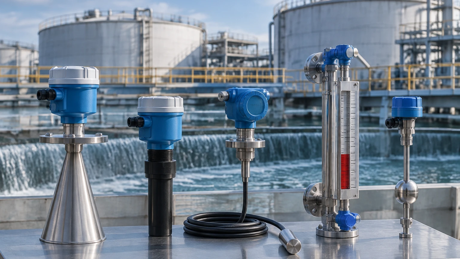
Before selecting a sensor, it is essential to understand the underlying physical principles that govern different measurement technologies. Most fill level sensors fall into two categories: non-contact and contact-based measurement.
Radar Level Measurement (Non-Contact)
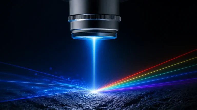
Radar level meters utilize high-frequency electromagnetic waves, typically in the 26 GHz or 80 GHz range. The sensor emits a signal toward the material surface, which reflects back to the antenna. By measuring the Time of Flight (ToF) or the frequency shift (FMCW), the device calculates the distance to the product surface.
Radar is highly versatile because electromagnetic waves are not significantly affected by temperature fluctuations, pressure changes, or the presence of vapors. High-frequency 80 GHz radar, in particular, offers a narrow beam angle, which is ideal for avoiding internal tank obstructions like agitators or heating coils.
Ultrasonic Level Measurement (Non-Contact)
Ultrasonic sensors function similarly to radar but use sound waves instead of electromagnetic pulses. The transducer emits an ultrasonic pulse that travels through the air, reflects off the surface of the media, and returns to the sensor. The distance is calculated based on the speed of sound.
While cost-effective and reliable for many water-based applications, ultrasonic sensors are sensitive to the composition of the gas space. Changes in temperature or the presence of heavy vapors can alter the speed of sound, requiring temperature compensation for accurate readings.
Hydrostatic Pressure Measurement (Contact)
Hydrostatic level transmitters measure the pressure exerted by a liquid column at a specific depth. Based on the principle that pressure ($P$) equals the density of the liquid ($ρ$) multiplied by gravity ($g$) and the height of the liquid ($h$), the sensor converts the measured pressure into a level reading.
This method is highly effective for vented tanks and deep wells. However, because the calculation depends on fluid density, any significant change in the temperature or composition of the liquid can introduce errors unless the system is calibrated for those specific variables.
Magnetic Level Gauges and Switches (Contact)
Magnetic level gauges utilize a float containing a permanent magnet that moves with the liquid level inside a bypass chamber. This magnet interacts with external flags or a sensing rod to provide a visual or electronic indication of the level. Level switches, on the other hand, provide point-level detection (e.g., high-level or low-level alarms) using various technologies like vibrating forks or float mechanisms.
Key Evaluation Criteria for Sensor Selection
To ensure long-term reliability, engineers must evaluate several factors before finalizing a sensor specification. For a comprehensive look at available technology options, you may Review product options and application support to match these criteria with specific hardware.
1. Media Characteristics: Is the material corrosive, viscous, or prone to foaming? Corrosive chemicals require PTFE or PVDF wetted parts. Foaming surfaces may absorb ultrasonic waves, making radar a better choice.
2. Process Conditions: What are the maximum operating temperatures and pressures? Ultrasonic sensors are generally limited to atmospheric or low-pressure applications, whereas radar and hydrostatic sensors can handle high-pressure environments exceeding 40 bar (580 psi).
3. Accuracy Requirements: Do you need millimeter-level precision for custody transfer, or is a 1% margin of error acceptable for general inventory? Radar typically offers the highest precision, often within ±2 mm (0.078 inches).
4. Tank Geometry: Narrow tanks or those with internal structures require sensors with narrow beam angles to prevent false reflections.
5. Installation Constraints: Is there a top-mounting port available, or is a side-mount or submersible sensor required?
Technology Comparison Table
| Technology | Typical Accuracy | Max Range | Best For | Limitations |
| :— | :— | :— | :— | :— |
| 80 GHz Radar | ±2 mm | 120 m (393 ft) | Corrosive liquids, solids, high precision | High initial cost |
| Ultrasonic | ±0.25% of range | 15 m (49 ft) | Water, wastewater, open channels | Affected by foam and heavy vapor |
| Hydrostatic | ±0.1% to ±0.5% | 200 m (656 ft) | Deep wells, vented tanks, oils | Sensitive to density changes |
| Magnetic Gauge| ±5 mm to ±10 mm | 6 m (19.6 ft) | Boiler drums, toxic fluids | Moving parts can wear over time |
Installation Considerations and Best Practices
Even the most advanced fill level sensor will fail to provide accurate data if installed incorrectly. Proper mounting is the foundation of a reliable measurement system.
Avoiding the "Dead Zone"
Every non-contact sensor has a "dead zone" or "blocking distance" near the face of the transducer. If the liquid level rises into this zone, the sensor cannot process the return signal correctly. Ensure the sensor is mounted high enough so that the maximum fill level never enters this dead zone.
Nozzle and Obstruction Management
When mounting a radar or ultrasonic sensor on a nozzle, the nozzle's height and diameter must be considered. If the nozzle is too narrow or too long, it can cause signal interference. Furthermore, sensors should be positioned away from the tank wall (typically at least 200 mm or 8 inches) and away from the inflow stream to avoid turbulence and false echoes.
Alignment and Leveling
For non-contact sensors, the transducer face must be parallel to the surface of the media. If the sensor is tilted, the signal may reflect away from the receiver, resulting in a "lost signal" error. In silos containing solids, aiming flanges may be necessary to align the sensor with the angle of repose of the material.
Common Risks and Limitations
Understanding the limitations of fill level sensors is crucial for risk mitigation in industrial environments.
* Foam Interference: Foam on the surface of a liquid can act as an insulator for ultrasonic waves and some radar frequencies. In heavy foam applications, a high-frequency radar or a contact-based hydrostatic sensor is usually preferred.
* Vapor and Condensation: Condensation on the face of an ultrasonic transducer can block the sound pulse. Some sensors feature a self-cleaning effect through vibration, but in high-moisture environments, radar with a flat-face antenna is often more resilient.
* Dust and Turbulence: In solid silos, dust can attenuate ultrasonic signals. Radar is generally unaffected by dust. For turbulent liquids, software filtering (damping) can help smooth out the readings, but the physical mounting should still aim for the calmest part of the vessel.
* Dielectric Constant (DC): Radar sensors rely on the dielectric constant of the material to reflect the signal. Materials with very low DC (like some oils or liquefied gases) reflect less energy. Modern high-sensitivity radar can handle low DC values, but this must be verified during the selection process.
Frequently Asked Questions (FAQ)
Q: Can I use an ultrasonic fill level sensor in a vacuum?
No. Ultrasonic waves require a medium (air or gas) to travel. In a vacuum, there is no medium to carry the sound, so the sensor will not function. Radar is the preferred choice for vacuum applications.
Q: How do I measure the level of a liquid with changing density?
If you are using a hydrostatic sensor, density changes will directly affect the accuracy. You should either use a radar sensor (which is independent of density) or employ a dual-sensor system that compensates for density changes in real-time.
Q: What is the benefit of 80 GHz radar over 26 GHz?
The primary benefit is the narrower beam angle. An 80 GHz sensor can focus its energy into a very tight beam, allowing it to "see" past internal obstructions and work more effectively in narrow tanks or through small nozzles.
Q: Are fill level sensors compatible with hazardous environments?
Yes, many sensors are available with Intrinsically Safe (IS) or Explosion-Proof (Ex-d) ratings. It is vital to check the local certification requirements (such as ATEX, IECEx, or UL) before installation in hazardous zones.
Conclusion and Next Steps
Selecting the right fill level sensor is a balance of technical requirements, environmental factors, and budget. By understanding the principles of radar, ultrasonic, and hydrostatic measurement, engineers can avoid common pitfalls and ensure a stable, accurate monitoring system.
When planning a project, always confirm the chemical compatibility of wetted parts, the expected temperature ranges, and the physical layout of the vessel. For those requiring specific technical data or customized OEM/ODM solutions, visiting the Main Page of a professional manufacturer like Welk is the best way to access detailed product specifications and expert application support. Proper selection today prevents costly downtime and maintenance issues tomorrow.