Mechanical Level Switch
Mechanical Level Switch
In the landscape of industrial automation and process control, the mechanical level switch remains a foundational technology for point-level detection. Despite the rise of electronic and non-contact sensing methods, mechanical switches are favored for their simplicity, reliability, and ability to operate without complex power requirements in many configurations. This guide provides an engineering perspective on the selection, application, and installation of mechanical level switches in modern industrial environments.
Understanding the Operating Principles
Before selecting a device, it is essential to understand the physics governing mechanical level switches. These instruments rely on physical displacement or resistance to trigger an electrical signal. The most common principles include buoyancy and torque resistance.
The Principle of Buoyancy
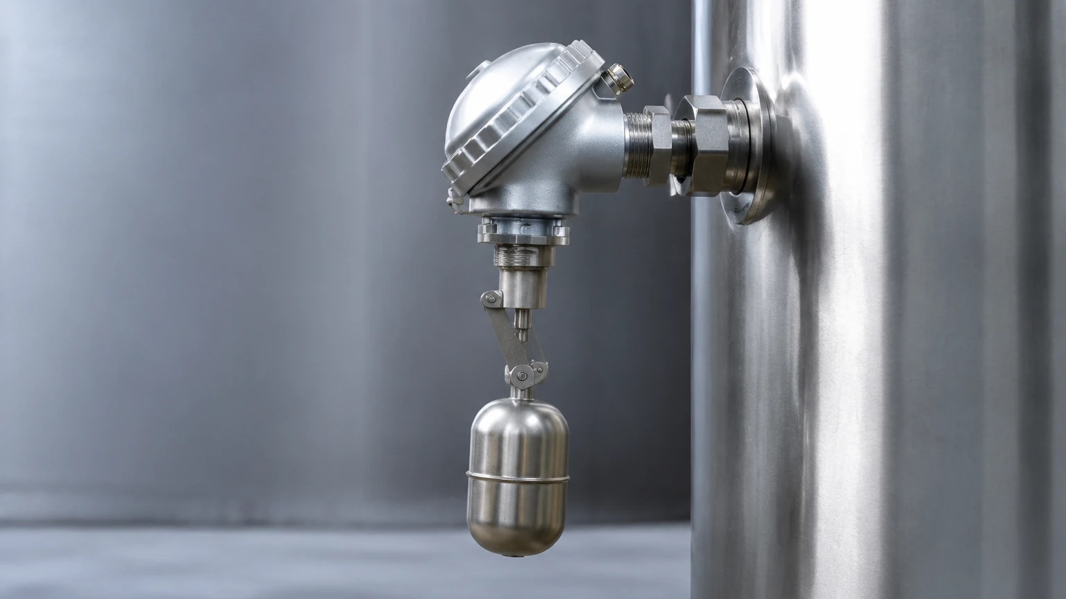
Most liquid-based mechanical level switches operate on Archimedes' principle. A float, designed with a lower density than the process liquid, remains on the surface. As the liquid level rises or falls, the float moves accordingly. This movement is then translated into a switching action through a mechanical linkage or a magnetic coupling. In magnetic designs, the float contains a permanent magnet that actuates a reed switch or a microswitch housed within a sealed stem or enclosure. This isolation ensures that the electrical components are never in contact with the process medium.
Displacer Principle
Unlike a float that sits on the surface, a displacer is heavier than the liquid and is suspended by a spring. When the liquid reaches the displacer, the buoyant force reduces the apparent weight of the displacer, causing the spring to retract slightly. This small movement is enough to actuate a switch. Displacers are particularly effective in turbulent liquids where a standard float might bounce excessively.
Rotating Paddle Principle
For solid materials, such as powders or granules, the mechanical level switch operates on the principle of torque resistance. A low-speed motor rotates a paddle. When the material level reaches the paddle, it restricts the rotation. The resulting torque causes the motor to shift on its mounting, tripping a microswitch that stops the motor and signals a high-level alarm.
Key Types of Mechanical Level Switches
Mechanical level switches are categorized based on their mounting style and the specific mechanical action they employ. Choosing the right type depends heavily on the vessel geometry and the physical state of the medium.
1. Horizontal Float Switches
These are typically side-mounted through the wall of a tank. They consist of a float attached to a hinged arm. As the level rises, the arm pivots, moving a magnet toward a switch. These are ideal for high or low-level alarms in small tanks where top access is limited.
2. Vertical Float Switches
Top-mounted on the vessel, these switches feature a float that moves up and down a vertical stem. The stem contains one or more reed switches at specific set points. This design allows for multi-point detection (e.g., high-high, high, low, and low-low levels) using a single process connection.
3. Heavy-Duty Cable Float Switches
Often used in water treatment and sewage applications, these consist of a large float housing a microswitch, connected to a flexible cable. The switch triggers when the float tilts beyond a certain angle. They are robust and highly resistant to fouling in wastewater environments.
4. Rotary Paddle Switches
Specifically designed for silos and bins containing bulk solids. They are available with various paddle shapes to accommodate different material densities, from light plastic pellets to heavy ores.
Technical Selection Criteria
Selecting a mechanical level switch requires a thorough evaluation of the process conditions. Failure to account for these variables can lead to premature mechanical failure or false readings.
* Medium Density (Specific Gravity): For float-based switches, the float must be lighter than the liquid. Most standard floats are designed for a specific gravity (SG) of 0.8 or higher. For low-density hydrocarbons, specialized high-buoyancy floats are required.
* Operating Pressure: The float must be able to withstand the process pressure without collapsing. Standard stainless steel floats can typically handle up to 30 bar (approx. 435 psi), but high-pressure variants are available for oil and gas applications.
* Temperature Limits: Mechanical switches can handle extreme temperatures, but the materials must be compatible. For example, PTFE or stainless steel components are necessary for high-temperature chemical processes exceeding 150°C.
* Viscosity and Coating: Mechanical parts are susceptible to sticking. If the medium is highly viscous or prone to crystallization, a non-contact method or a heavy-duty displacer may be more appropriate than a small float switch.
Selection Table for Mechanical Level Switches
| Switch Type | Application | Max Temperature (Typical) | Max Pressure (Typical) | Best For |
| :— | :— | :— | :— | :— |
| Side-Mounted Float | Liquids | 200°C | 40 bar | Small tanks, side entry |
| Vertical Multi-Point | Liquids | 150°C | 30 bar | Multiple set points |
| Cable Tilt Switch | Wastewater | 80°C | Atmospheric | Sumps, large basins |
| Displacer Switch | Turbulent Liquids | 250°C | 100 bar | High pressure, turbulence |
| Rotary Paddle | Bulk Solids | 80°C (Standard) | Atmospheric | Silos, hopper bins |
Installation Considerations and Best Practices
Correct installation is critical for the longevity of a mechanical level switch. Engineers should follow these guidelines to ensure reliable operation:
1. Avoid Turbulence: Do not install float switches directly near high-velocity inlet pipes. The resulting turbulence can cause the float to chatter, leading to rapid wear of the mechanical linkage or electrical contacts. If installation near an inlet is unavoidable, use a stilling well (a perforated pipe) to dampen the liquid movement.
2. Orientation: Ensure that side-mounted switches are perfectly horizontal and vertical switches are plumb. Even a few degrees of misalignment can increase friction in the pivot points, causing the switch to stick.
3. Clearance: Verify that the float has sufficient room to move through its entire stroke without hitting tank walls, baffles, or internal heating coils.
4. Wiring and Sealing: Use appropriate cable glands to maintain the IP rating of the enclosure. In outdoor installations, always include a drip loop in the wiring to prevent moisture from entering the housing.
Limitations and Common Risks
While mechanical level switches are robust, they are not "fit and forget" devices. They have inherent limitations that must be managed:
* Mechanical Wear: Because they have moving parts, they will eventually wear out. Regular inspection of pivots and springs is necessary, especially in high-cycle applications.
* Material Build-up: In applications involving slurries or sticky fluids, material can accumulate on the float or paddle. This increases the weight of the float or jams the paddle, leading to a failure to switch.
* Sensitivity to Density Changes: If a process involves different liquids with varying densities, a float calibrated for a heavy liquid may not rise in a lighter one.
For more complex applications or to explore a wider range of measurement technologies, engineers can visit the Main Page to compare mechanical options with electronic alternatives like radar or ultrasonic sensors.
Frequently Asked Questions (FAQs)
Q: Can mechanical level switches be used in hazardous areas?
A: Yes, many mechanical switches are available with explosion-proof enclosures or can be used in intrinsically safe circuits (using a Zener barrier), as the switch itself is often a "simple apparatus."
Q: How often should a mechanical level switch be calibrated?
A: Mechanical switches do not require calibration in the same way electronic sensors do, but they should be "functional tested" every 6 to 12 months to ensure the moving parts transition freely and the electrical contacts close/open correctly.
Q: What is the difference between a reed switch and a microswitch in a float?
A: A reed switch is hermetically sealed and actuated by a magnet; it is ideal for low-power signaling. A microswitch is a mechanical snap-action switch that can often handle higher current loads directly, such as starting a small pump.
Conclusion
The mechanical level switch remains a vital tool in the industrial engineer's toolkit. By understanding the physical principles of buoyancy and torque, and by carefully matching the switch materials and design to the process environment, users can achieve highly reliable point-level control. Whether managing a simple water sump or a high-pressure chemical reactor, these devices offer a cost-effective and understandable solution for level detection. For those seeking comprehensive industrial measurement solutions, reviewing the latest product specifications on the Main Page is recommended to ensure the selected technology meets the specific demands of the application.