Flow Assembly
Flow Assembly
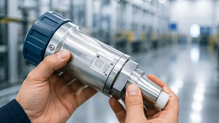
In the realm of industrial process control, a flow assembly serves as the critical mechanical interface between a process medium and the instrumentation used to monitor it. While often associated with flow meters, the concept of a flow assembly is equally vital in level measurement, particularly when dealing with bypass chambers, external cages, and stilling wells. These assemblies are engineered to provide a stable environment for sensors, protecting them from turbulence, foam, and internal tank obstructions while ensuring that the measurement reflects the true state of the process.
For engineers and plant operators, selecting the correct flow assembly is not merely a secondary concern; it is a fundamental requirement for system accuracy and longevity. Whether managing water treatment facilities or high-pressure chemical reactors, understanding the structural and fluid dynamic principles of these assemblies is essential for optimizing plant performance.
Measurement Principles in Assembly Design
Before selecting a specific flow assembly, it is necessary to understand how different measurement technologies interact with the assembly structure. Most industrial level instruments, such as those found on the Main Page of specialized manufacturers, rely on specific physical principles that the assembly must accommodate.
Communicating Vessels Principle
In bypass level indicators and external cages, the flow assembly operates on the principle of communicating vessels. By connecting a vertical chamber to the side of a tank via two or more process connections, the liquid level in the chamber equalizes with the level in the main vessel. This allows instruments like magnetic level gauges or guided wave radar (GWR) sensors to measure the level in a controlled, static environment, isolated from the agitation or steam present in the main tank.
Signal Propagation and Reflection
For non-contact technologies like radar or ultrasonic sensors, the flow assembly (often in the form of a stilling well) acts as a waveguide. In a large, turbulent tank, signal scattering can lead to false echoes. A properly designed pipe assembly directs the electromagnetic or acoustic waves, concentrating the energy on the fluid surface and ensuring a strong, clear return signal. This is particularly important for fluids with low dielectric constants or those prone to surface rippling.
Hydrostatic Pressure
When a flow assembly is used with hydrostatic transmitters, the assembly must ensure that the sensor is exposed to the full head of the liquid without being influenced by the velocity of the fluid (dynamic pressure). In these cases, the assembly often includes features to dampen surges and prevent the "pitot tube effect," which can cause artificial pressure spikes in high-velocity lines.
Types of Flow Assemblies
Industrial applications require different assembly configurations based on the physical constraints of the vessel and the nature of the medium. The following table provides a comparison of common flow assembly types used in level and flow monitoring.
Selection Table: Flow Assembly Configurations
| Assembly Type | Primary Application | Measurement Technology | Key Advantage |
| :— | :— | :— | :— |
| Bypass Chamber | External level monitoring | Magnetic gauges, Radar | Easy maintenance without process shutdown |
| Stilling Well | Internal level measurement | Ultrasonic, Radar | Eliminates foam and turbulence interference |
| Flow-Through Cell | Inline liquid analysis | Conductivity, pH, Flow | Continuous monitoring of flowing media |
| External Cage | High-pressure boilers | Displacers, GWR | Robust mechanical protection in extreme heat |
| In-line Flow Assembly | Pipe-integrated monitoring | Electromagnetic, Vortex | Minimal pressure drop and high accuracy |
Material Science and Construction Standards
The integrity of a flow assembly is dictated by its materials. Because these components are often under the same pressure and temperature stresses as the main process vessel, they must adhere to strict metallurgical standards.
1. Stainless Steel (316L/304): The standard for water treatment and general chemical applications due to its corrosion resistance and cost-effectiveness.
2. Exotic Alloys (Hastelloy, Monel, Inconel): Required for highly corrosive media like sulfuric acid or in offshore environments where salt spray is a factor.
3. Plastics (PVC, CPVC, PVDF): Used in low-pressure, highly acidic, or alkaline environments where metallic components would fail rapidly.
Construction typically follows ASME B31.3 for process piping or specialized pressure vessel codes. Welding quality is paramount; many high-spec flow assemblies undergo X-ray testing and dye penetrant inspection to ensure no micro-fissures exist that could lead to catastrophic failure under high-pressure cycles.
Installation Considerations
A flow assembly is only as effective as its installation. Poor placement can lead to measurement lag, air trapping, or sediment buildup.
Orientation and Alignment
For bypass and stilling well assemblies, verticality is non-negotiable. A deviation of even a few degrees can cause a magnetic float to bind against the chamber wall or cause a radar signal to reflect off the side of the pipe rather than the fluid surface. Standard engineering practice requires these assemblies to be plumb within 1 mm per meter of length.
Venting and Draining
Every flow assembly should be equipped with high-point vents and low-point drains. Vents prevent air pockets from forming, which can interfere with the liquid level equalization. Drains are essential for maintenance, allowing the assembly to be flushed of sediment or emptied before a sensor is removed for calibration.
Isolation Valves
One of the primary benefits of an external flow assembly is the ability to isolate the instrument from the process. High-quality ball or gate valves should be installed between the vessel and the assembly. This allows for "hot-swapping" of instruments or routine cleaning without needing to drain the entire tank, significantly reducing downtime in 24/7 industrial operations.

Limitations and Risks
While flow assemblies solve many measurement problems, they introduce their own set of challenges that must be managed.
* Sedimentation and Clogging: In fluids with high solids content, the narrow passages of a flow assembly can become blocked. This results in a "frozen" reading where the level in the assembly no longer matches the level in the tank.
* Thermal Expansion: In high-temperature applications, the assembly may expand at a different rate than the vessel. If not properly supported with expansion loops or sliding mounts, the resulting stress can crack welds or flanges.
* Coating and Scaling: For radar and ultrasonic sensors, the buildup of scale on the interior walls of the assembly pipe can create "ghost echoes." Regular inspection and the use of PTFE-lined assemblies can mitigate this risk.
* Viscosity Limits: Highly viscous liquids may move too slowly through the bypass connections, leading to a significant time lag in measurement. For fluids over 500 cP, larger diameter connections (e.g., 50 mm or 80 mm) are typically required.
Frequently Asked Questions (FAQ)
Q: How do I determine the correct diameter for a stilling well flow assembly?
A: The diameter depends on the sensor type. For radar, a diameter of 50 mm to 100 mm is common. It must be large enough to avoid signal interference from the walls but small enough to effectively dampen surface turbulence.
Q: Can a flow assembly be used for interface measurement (e.g., oil and water)?
A: Yes, bypass chambers are frequently used for interface measurement. However, the float (in magnetic systems) must be precisely weighted to sink through the upper liquid and float on the lower liquid. For radar, the assembly must be designed to minimize signal attenuation at the interface layer.
Q: What is the maintenance schedule for a standard flow assembly?
A: In clean water applications, an annual inspection is usually sufficient. In chemical or wastewater applications, quarterly flushing through the drain valve is recommended to prevent the accumulation of sludge or scale.
Q: Are there pressure limits for plastic flow assemblies?
A: Yes, plastic assemblies like PVC or PVDF are generally limited to lower pressures (often below 10 bar) and temperatures (below 60°C for PVC). Always consult the pressure-temperature derating curves provided by the manufacturer.
Conclusion
The integration of a robust flow assembly into an industrial process is a hallmark of sound engineering. By providing a stable, accessible, and protected environment for sensitive instrumentation, these assemblies ensure that data remains accurate and reliable over the long term. When selecting an assembly, engineers must weigh the chemical properties of the medium against the physical requirements of the sensor, ensuring that materials, dimensions, and installation methods align with the specific needs of the application. For those seeking to optimize their measurement systems, consulting with a professional manufacturer can provide the technical clarity needed to choose the right components for complex industrial environments.