Flow Meter Instrumentation
Flow Meter Instrumentation
In the landscape of industrial automation and process control, flow meter instrumentation serves as a critical pillar for operational efficiency, safety, and fiscal accountability. Whether managing water treatment facilities, chemical processing plants, or oil and gas refineries, the ability to accurately quantify the movement of liquids, gases, and steam is essential. Selecting the appropriate flow meter requires a deep understanding of fluid dynamics, the physical properties of the medium, and the specific constraints of the installation environment.
While level measurement focuses on the volume of fluid contained within a vessel, flow meter instrumentation tracks the rate of transfer between points. Together, these technologies provide a comprehensive view of mass balance within a facility. This guide explores the fundamental principles of flow measurement, practical selection criteria, and the engineering considerations necessary for successful deployment.
Understanding Flow Meter Instrumentation Principles
Before selecting a specific instrument, it is necessary to understand the physics governing different measurement technologies. Flow meters are generally categorized by the physical principle they employ to derive flow rate.
Differential Pressure (DP) Meters
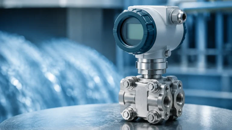
Differential pressure is one of the most established methods in flow meter instrumentation. It operates on Bernoulli’s principle, which states that as the speed of a moving fluid increases, the pressure within the fluid decreases. By placing a primary element—such as an orifice plate, Venturi tube, or flow nozzle—inside the pipe, a pressure drop is intentionally created. A secondary element, the DP transmitter, measures the difference between the upstream and downstream pressures. The flow rate is proportional to the square root of this pressure difference.
Electromagnetic Flow Meters (Magmeters)
Magmeters operate based on Faraday’s Law of Induction. When a conductive liquid flows through a magnetic field generated by the meter, it produces a voltage proportional to its velocity. This technology is highly effective for water, wastewater, and corrosive slurries because it has no moving parts and creates no pressure drop. However, it requires the fluid to have a minimum conductivity, typically >5 μS/cm, making it unsuitable for hydrocarbons or deionized water.
Ultrasonic Flow Meters
Ultrasonic instrumentation uses sound waves to determine flow velocity. There are two primary types:
1. Transit-Time: These meters send pulses back and forth across the pipe. The pulse traveling with the flow moves faster than the pulse traveling against it. The time difference (delta-T) is used to calculate velocity. These are best for clean liquids.
2. Doppler: These reflect sound waves off bubbles or particles in the fluid. The frequency shift (Doppler effect) indicates the velocity. These are ideal for aerated liquids or slurries.
Vortex Flow Meters
Vortex meters utilize the Karman Vortex Street principle. As fluid flows past a "shedder bar" placed in the stream, vortices (swirls) are formed alternately on each side. The frequency at which these vortices are shed is directly proportional to the fluid velocity. These meters are robust and widely used for steam and gas measurement due to their lack of moving parts and high-temperature tolerance.
Key Evaluation Criteria for Flow Meter Selection
Choosing the right flow meter instrumentation involves more than matching a pipe size. Engineers must evaluate the chemical and physical properties of the process medium alongside the operational goals of the system.
Fluid Properties and Phase
The state of the fluid—liquid, gas, or steam—is the first filter in selection. For liquids, viscosity and conductivity are paramount. High-viscosity fluids may require positive displacement or Coriolis meters, while conductive fluids are ideal for electromagnetic meters. For gases, compressibility must be accounted for, often requiring pressure and temperature compensation to provide accurate mass flow data.
Flow Profile and Reynolds Number
The Reynolds number (Re) is a dimensionless value that defines whether flow is laminar, transitional, or turbulent. Most flow meter instrumentation, particularly DP and Vortex meters, requires a fully developed turbulent flow profile (typically Re > 10,000) to maintain accuracy. If the flow is laminar, different calibration factors or technologies must be applied.
Accuracy vs. Repeatability
In B2B industrial contexts, it is vital to distinguish between accuracy (how close the reading is to the true value) and repeatability (how consistent the readings are under identical conditions). For custody transfer, high accuracy (e.g., ±0.1% to ±0.5%) is required. For simple process control or pump protection, repeatability may be more important than absolute accuracy.
Comparison of Flow Measurement Technologies
The following table provides a practical reference for comparing common flow meter types used in industrial applications.
| Technology | Suitable Fluids | Typical Accuracy | Pressure Drop | Key Advantage |
| :— | :— | :— | :— | :— |
| Differential Pressure | Liquids, Gas, Steam | ±0.5% to ±2% | Medium to High | Low cost, well-understood |
| Electromagnetic | Conductive Liquids | ±0.2% to ±0.5% | Negligible | No moving parts, handles slurries |
| Ultrasonic | Clean/Dirty Liquids | ±0.5% to ±1% | None | Non-intrusive (clamp-on options) |
| Vortex | Liquids, Gas, Steam | ±0.7% to ±1% | Low to Medium | Excellent for high-temp steam |
| Coriolis | Liquids, High-Visc | ±0.1% | Medium | Direct mass flow measurement |
| Turbine | Clean Liquids, Gas | ±0.25% to ±0.5% | High | High precision for clean fluids |
Installation Best Practices and Engineering Considerations
The performance of flow meter instrumentation is heavily dependent on the installation environment. Even the most expensive meter will fail to meet its accuracy specifications if installed incorrectly.
Straight Pipe Run Requirements
Most flow meters require a certain length of straight pipe upstream and downstream of the sensor to eliminate turbulence caused by elbows, valves, or pumps. A common rule of thumb is "10D Upstream / 5D Downstream," where D is the pipe diameter. For example, a 100 mm pipe would require 1000 mm of straight pipe before the meter and 500 mm after it. If space is limited, flow conditioners or specific meter types (like certain ultrasonic or magmeters) may be used to reduce these requirements.
Orientation and Mounting
* Liquid Service: Meters should be installed in a low point or a rising vertical pipe to ensure the sensor remains full of liquid. Trapped air pockets can cause significant errors or signal loss.
* Gas Service: Meters should be installed at high points to prevent condensate from pooling in the sensor.
* Grounding: For electromagnetic meters, proper grounding is essential. The fluid, the meter body, and the transmitter must be at the same electrical potential to prevent noise from interfering with the low-voltage measurement signal.
Environmental Factors
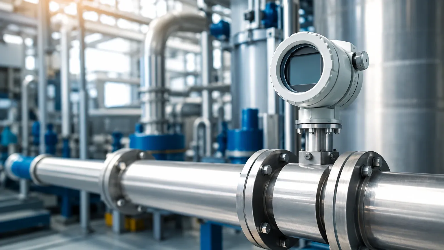
Industrial environments often subject instrumentation to vibration, electromagnetic interference (EMI), and extreme temperatures. Transmitters should be mounted in accessible locations, and if the process temperature exceeds the electronics' rating, remote-mounted electronics should be utilized.
Common Risks and Operational Limitations
Identifying potential failure points early can prevent costly downtime and equipment damage.
1. Cavitation and Flashing: In liquid applications, if the pressure drops below the vapor pressure of the fluid, vapor bubbles form (cavitation) and then collapse. This can erode the meter internals and cause erratic readings. Proper back-pressure must be maintained.
2. Entrained Air: In ultrasonic and electromagnetic meters, air bubbles can scatter signals or change the perceived volume, leading to over-reading or signal "walk-out."
3. Scaling and Coating: In chemical and wastewater applications, buildup on the electrodes of a magmeter or the shedder bar of a vortex meter can degrade accuracy over time. Regular maintenance or the use of non-contacting ultrasonic meters may be necessary in these scenarios.
4. Turndown Ratio Limits: Every meter has a minimum and maximum flow rate it can measure accurately. Operating outside this "turndown ratio" (e.g., 10:1 or 100:1) results in a loss of precision, particularly at the low end of the scale.
Integrating Flow and Level Measurement Systems
In complex industrial processes, flow meter instrumentation and level measurement instruments work in tandem. For instance, in a chemical dosing system, a level transmitter monitors the inventory in the supply tank, while a flow meter ensures the precise amount of chemical is delivered to the process.
Welk provides specialized solutions for these integrated environments, focusing on robust level measurement that complements flow data. For engineers looking to optimize their entire measurement loop, it is helpful to Review product options and application support to ensure that both level and flow instruments are compatible with the process chemistry and communication protocols (such as HART, Modbus, or Profibus) used in the plant.
Frequently Asked Questions (FAQ)
Q: Can I use an electromagnetic flow meter for oil?
A: Generally, no. Crude oil and refined petroleum products have very low conductivity. Magmeters require a conductive fluid to generate the necessary voltage for measurement.
Q: What is the difference between mass flow and volumetric flow?
A: Volumetric flow measures the space the fluid occupies (e.g., liters per minute), which changes with temperature and pressure. Mass flow measures the actual amount of matter (e.g., kilograms per minute), which remains constant regardless of environmental changes. Coriolis meters measure mass flow directly.
Q: Why is my ultrasonic flow meter giving inconsistent readings?
A: This is often due to an undeveloped flow profile or entrained air. Ensure you have met the straight-run requirements and that the pipe is completely full of liquid. For clamp-on meters, ensure the acoustic coupling gel has not dried out.
Q: How often should flow meter instrumentation be calibrated?
A: Calibration frequency depends on the criticality of the measurement and the aggressiveness of the fluid. For most industrial applications, an annual calibration check is standard, though custody transfer applications may require more frequent verification.
By adhering to these engineering principles and carefully matching technology to the application, operators can ensure that their flow meter instrumentation provides the reliable data necessary for modern industrial success. For more detailed technical specifications on level and flow integration, visit the Main Page for comprehensive product data.