Flow Transducers
Flow Transducers
In the landscape of industrial process control, flow transducers serve as the primary sensory organs for monitoring the movement of liquids and gases through piping systems. While level measurement provides critical data regarding the volume of material stored in a vessel, flow transducers provide the dynamic data of how that material is entering or leaving the system. For engineers and facility managers, understanding the operational mechanics, selection criteria, and installation nuances of these instruments is essential for maintaining process efficiency and safety.
Industrial flow measurement is rarely a stand-alone requirement. It is often integrated with level measurement technologies—such as radar or ultrasonic sensors—to provide a comprehensive view of mass balance. For those seeking a broad range of industrial instrumentation, including radar level meters and integrated sensors, the Main Page of specialized manufacturers provides a foundational reference for equipment selection.
Measurement Principles of Flow Transducers
Before selecting a specific instrument, it is necessary to understand the physical principles that govern flow measurement. Flow transducers do not measure "flow" directly; instead, they measure a physical property influenced by the fluid's movement and convert that into a standardized electrical signal (typically 4-20mA, 0-10V, or digital protocols like Modbus).
Differential Pressure (DP)
Differential pressure remains one of the most common principles. It relies on Bernoulli’s equation, which states that as the speed of a moving fluid increases, the pressure within the fluid decreases. By placing a restriction in the pipe (such as an orifice plate, Venturi tube, or nozzle), a pressure drop is created. The transducer measures the pressure before and after the restriction. The square root of this pressure difference is proportional to the flow rate.
Electromagnetic Induction
Often referred to as "mag meters," these transducers operate based on Faraday’s Law of Electromagnetic Induction. When a conductive liquid flows through a magnetic field generated by the transducer, it induces a voltage. This voltage is directly proportional to the velocity of the liquid. Because this method requires no moving parts and offers no restriction to the flow, it is ideal for slurries and corrosive liquids, provided the medium is electrically conductive (typically >5 μS/cm).
Ultrasonic (Transit-Time and Doppler)
Ultrasonic flow transducers use sound waves to determine velocity.
- Transit-Time: Two transducers send and receive ultrasonic pulses. The pulse traveling with the flow moves faster than the one traveling against it. The time difference is used to calculate velocity.
- Doppler: These sensors emit sound waves that reflect off particles or bubbles in the fluid. The frequency shift (Doppler effect) of the reflected signal determines the flow speed. This is preferred for "dirty" liquids.
Vortex Shedding
Based on the Von Kármán effect, a bluff body (shedder bar) is placed in the flow stream. As fluid passes this body, vortices are created and shed alternately on either side. The frequency at which these vortices are shed is directly proportional to the fluid velocity. This principle is highly effective for steam and low-viscosity liquids.
Technical Comparison and Selection
Selecting the correct flow transducer requires an analysis of the fluid properties, pipe size, and required accuracy. The following table provides a generalized comparison for industrial applications.
| Technology | Suitable Fluids | Accuracy (Typical) | Pressure Drop | Moving Parts |
| :— | :— | :— | :— | :— |
| Differential Pressure | Liquids, Gases, Steam | ±1.0% to ±2.0% | High | No |
| Electromagnetic | Conductive Liquids | ±0.2% to ±0.5% | Negligible | No |
| Ultrasonic | Clean/Dirty Liquids | ±0.5% to ±1.0% | None | No |
| Vortex | Steam, Gases, Low Viscosity | ±0.7% to ±1.0% | Medium | No |
| Turbine | Clean, Low Viscosity | ±0.2% to ±0.5% | High | Yes |
Installation Considerations for Flow Transducers
The performance of a flow transducer is heavily dependent on its installation environment. Even the most accurate sensor will provide erroneous data if the flow profile is turbulent or non-uniform.
Straight Pipe Requirements
Most flow transducers require a specific length of straight pipe upstream and downstream of the installation point to ensure a fully developed, laminar flow profile.
- Upstream: Typically 10 to 20 pipe diameters (D) of straight run are required after elbows, valves, or pumps.
- Downstream: Usually 5 pipe diameters (D) are sufficient to prevent back-pressure disturbances.
If the installation site lacks sufficient space, flow straighteners or vanes may be used to condition the fluid before it reaches the transducer.
Orientation and Filling
For liquid applications, the pipe must always be completely full. Installing a transducer in a vertical pipe with upward flow is often preferred to ensure the pipe remains full and to prevent air pockets. If installed horizontally, the sensor should not be placed at the very top of the pipe (where air collects) or the very bottom (where sediment accumulates).
Grounding and Interference
Electromagnetic flow transducers are particularly sensitive to electrical noise. Proper grounding to the process piping or the use of grounding rings is mandatory to isolate the micro-volt signals generated by the sensor from stray currents in the plant environment.
Limitations and Common Risks
While modern flow transducers are robust, certain conditions can lead to premature failure or measurement drift:
1. Cavitation: If the pressure at the transducer drops below the vapor pressure of the liquid, vapor bubbles form and collapse. This can erode the internal components of turbine or vortex meters and cause signal "noise" in ultrasonic units.
2. Viscosity Shifts: DP and turbine meters are sensitive to changes in viscosity. If a process involves temperature fluctuations that alter the fluid's thickness, the flow calibration may become invalid.
3. Scaling and Coating: In wastewater or chemical applications, material can build up on the electrodes of a mag meter or the pipe walls of an ultrasonic meter. This changes the internal diameter or insulates the sensors, leading to significant under-reading of flow rates.
4. Abrasive Fluids: High-velocity slurries can wear down the shedder bars in vortex meters or the internal lining of mag meters. Selecting appropriate liner materials, such as PTFE or PFA, is critical for longevity.
Integration with Level Measurement Systems
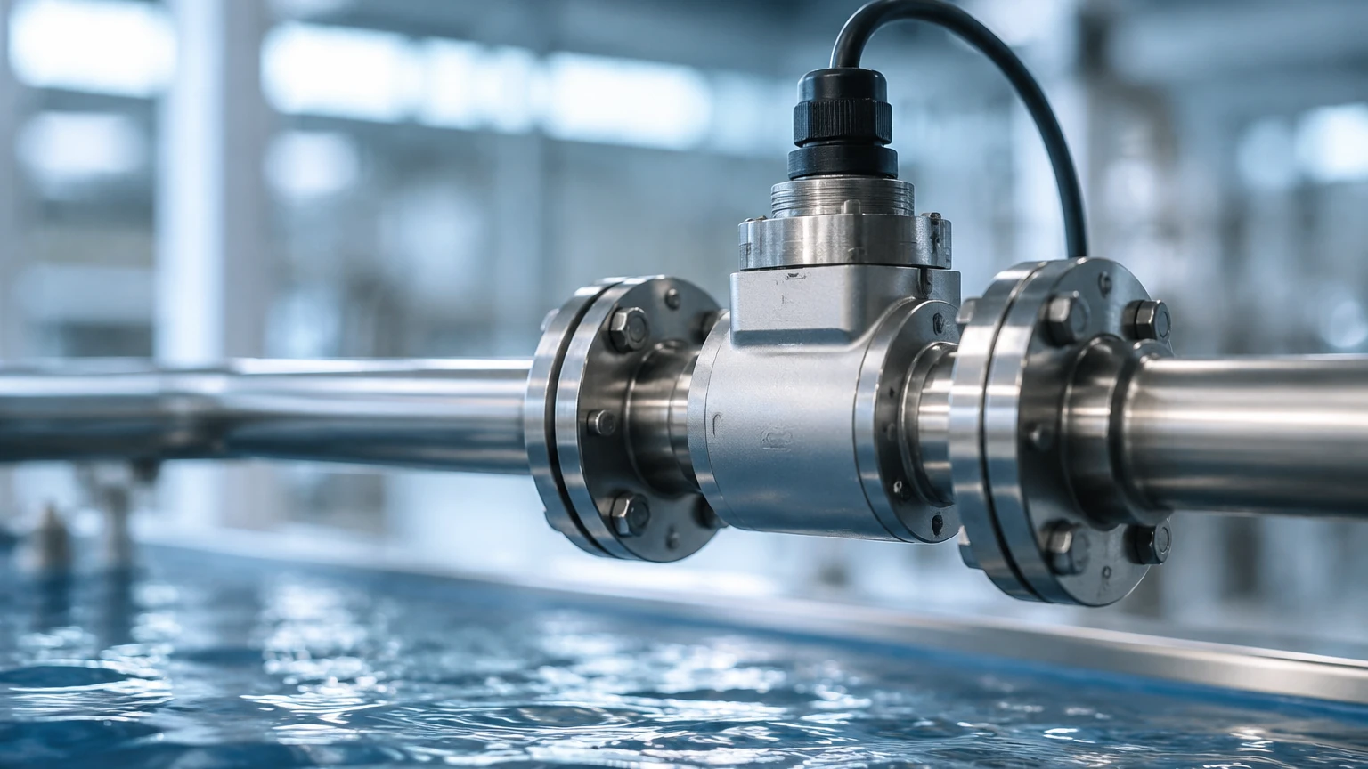
In many B2B industrial scenarios, flow transducers and level meters work in tandem. For example, in a chemical dosing tank, a radar level meter monitors the total volume available, while a flow transducer ensures the precise amount of chemical is being delivered to the process.
This synergy allows for "leak detection by mass balance." If the flow transducer at the outlet shows a higher volume leaving the system than the level meter indicates is missing from the tank, it suggests a discrepancy that requires immediate inspection. For comprehensive system design, engineers often consult the Main Page of equipment providers to ensure that the communication protocols of the flow and level instruments are compatible (e.g., both using HART or RS485).
Frequently Asked Questions (FAQ)
Q: Can a flow transducer measure both mass and volume?
Most standard flow transducers (Ultrasonic, Mag, Vortex) measure volumetric flow (m³/h). To obtain mass flow (kg/h), you must either use a Coriolis meter or combine the volumetric data with temperature and pressure measurements to calculate density.
Q: How often should flow transducers be recalibrated?
Calibration frequency depends on the criticality of the process and the fluid type. For regulated industries like pharmaceutical or food production, annual calibration is standard. In general industrial water treatment, a check every 24 months may suffice unless drift is detected.
Q: What is the "turn-down ratio"?
The turn-down ratio indicates the range over which the transducer can measure accurately. For example, a 10:1 turn-down ratio on a meter with a maximum capacity of 100 m³/h means it can measure accurately down to 10 m³/h. Below this, the signal becomes unreliable.
Q: Are clamp-on flow transducers as accurate as inline versions?
Clamp-on ultrasonic transducers offer the advantage of not breaking the pipe seal, which is ideal for retrofitting. However, they are generally slightly less accurate (±1.0% to ±2.0%) than inline versions because they are dependent on the user correctly inputting the pipe wall thickness and material properties.
Summary of Confirmation for Project Leads
Before finalizing a procurement order for flow transducers, project engineers should confirm the following data points:
- Fluid Conductivity: Essential for electromagnetic meters.
- Reynolds Number: Confirms if the flow is laminar or turbulent, affecting DP and vortex meter accuracy.
- Chemical Compatibility: Ensure the wetted parts (electrodes, liners, or shedder bars) are resistant to the process medium.
- Pipe Schedule: Accurate internal diameter (ID) is required for all volumetric calculations.
By adhering to these engineering principles and selection guidelines, facilities can ensure long-term reliability in their flow measurement infrastructure, complementing their existing level control systems for optimized industrial automation.