Flowline Map
Flowline Map
In the complex landscape of industrial process automation, a flowline map serves as the foundational blueprint for fluid management and instrumentation strategy. For engineers and plant managers, understanding the spatial and functional relationship between storage vessels, transport piping, and processing units is essential for maintaining operational safety and efficiency. A well-constructed flowline map does more than just chart the movement of media; it identifies the critical nodes where precise level measurement is required to prevent overflows, manage inventory, and protect downstream equipment.
At Welk, we recognize that the effectiveness of industrial level measurement instruments depends heavily on their strategic placement within this flowline architecture. Whether managing water treatment facilities, chemical processing plants, or oil and gas refineries, the integration of radar, ultrasonic, and hydrostatic sensors into the flowline map ensures that real-time data is available at every pivotal stage of the process.
Understanding Level Measurement Principles
Before determining where an instrument should be placed on a flowline map, it is necessary to understand the underlying physical principles of the technologies available. Each measurement method interacts differently with the process media and the physical environment of the tank or pipe.
Radar Level Measurement (Non-Contact)
Radar level meters operate on the Time-of-Flight (ToF) principle. The sensor emits high-frequency microwave pulses (typically in the 26GHz or 80GHz range) that travel at the speed of light. When these pulses hit the surface of the medium, they are reflected back to the antenna. The instrument calculates the distance based on the time interval between transmission and reception.
Because microwaves do not require a physical medium for propagation, radar sensors are largely unaffected by changes in temperature, pressure, or the presence of dust and vapors. This makes them a primary choice for critical nodes on a flowline map where high precision and reliability are non-negotiable.
Ultrasonic Level Measurement
Similar to radar, ultrasonic sensors use the ToF principle but utilize sound waves instead of electromagnetic waves. The sensor emits an ultrasonic pulse that reflects off the liquid surface. The time taken for the echo to return is proportional to the distance.
However, sound speed is influenced by air temperature and density. While modern ultrasonic sensors include temperature compensation, they are generally best suited for stable environments, such as open-channel flow or ambient-pressure water storage tanks. On a flowline map, these are often found in secondary stages or wastewater management sections.
Hydrostatic Level Measurement
Hydrostatic transmitters measure the pressure exerted by a liquid column at a specific depth. Based on the formula $P = \rho gh$ (where $P$ is pressure, $\rho$ is density, $g$ is gravity, and $h$ is height), the level can be accurately determined if the density of the fluid is constant. These sensors are typically submerged or mounted at the bottom of a vessel. They are highly effective for deep wells, vented tanks, and applications where the top of the vessel is cluttered with agitators or internal structures that might interfere with top-down technologies.
The Role of the Flowline Map in System Design
A flowline map acts as a diagnostic tool during the engineering phase. By visualizing the entire journey of a fluid—from intake to final output—engineers can identify "high-risk" zones. These zones include areas prone to rapid level changes, high turbulence, or chemical reactions that produce foam.
When populating a flowline map with instrumentation, designers must consider:
1. Inlet and Outlet Locations: Sensors should be positioned away from direct fill lines to avoid false readings caused by the incoming stream.
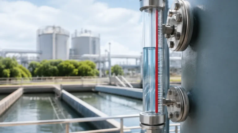
2. Bypass Requirements: In high-pressure or high-temperature applications, a magnetic level gauge or a bypass chamber might be mapped alongside the main vessel to allow for maintenance without shutting down the process.
3. Redundancy Points: For safety-instrumented systems (SIS), the flowline map will indicate where multiple technologies (e.g., a radar meter paired with a mechanical level switch) should be installed to provide fail-safe monitoring.
To explore the full range of hardware available for these applications, engineers can Review product options and application support to ensure their map is supported by the correct technical specifications.
Technical Selection Criteria for Flowline Nodes
Selecting the right instrument for a specific point on the flowline map requires an evaluation of the process conditions. The following table provides a comparison of common technologies used in industrial environments.
| Feature | Radar (80GHz) | Ultrasonic | Hydrostatic | Magnetic Gauge |
| :— | :— | :— | :— | :— |
| Measurement Type | Non-contact | Non-contact | Contact (Pressure) | Contact (Buoyancy) |
| Accuracy | ±1 mm | ±0.25% of range | ±0.1% to 0.5% | ±5 mm to 10 mm |
| Max Range | Up to 120m | Up to 30m | Up to 200m (Cable) | Up to 6m (Standard) |
| Pressure Limit | Up to 160 bar | Ambient/Low | High (Submersible) | Up to 320 bar |
| Temp Limit | -40°C to +450°C | -40°C to +80°C | -20°C to +100°C | Up to +450°C |
| Foam Resistance | Excellent (High freq) | Poor | Excellent | Good |
Installation Considerations and Best Practices
Even the most advanced sensor will fail to provide accurate data if the installation does not align with the physical realities of the flowline map. Below are critical considerations for deploying level instruments:
Dead Zones (Blocking Distance)
Every top-down sensor (radar and ultrasonic) has a "dead zone" directly beneath the antenna where measurement is impossible. When mapping a tank, the sensor must be mounted high enough that the maximum expected liquid level does not enter this zone. For ultrasonic sensors, this zone is typically 0.25m to 0.8m, while high-frequency radar sensors have significantly smaller dead zones (often less than 0.1m).
Nozzle Geometry
The mounting nozzle on a tank can act as a source of interference. If the nozzle is too narrow or too long, the signal may reflect off the nozzle walls rather than the liquid surface. For radar installations, the antenna should ideally extend slightly past the nozzle end, or the software must be configured with a "false echo suppression" map to ignore these static reflections.
Turbulence and Agitation
In many industrial processes, fluids are constantly stirred. This creates a non-level surface and potentially vortexing. In these scenarios, using a stilling well (a pipe installed inside the tank to provide a calm surface for measurement) is often necessary. The flowline map should clearly indicate which vessels require stilling wells to ensure the correct hardware is ordered.

Limitations and Operational Risks
While modern instrumentation is robust, certain environmental factors can compromise the integrity of the data on your flowline map:
* Heavy Foam: Foam can absorb ultrasonic and radar signals. In cases of dense, thick foam, hydrostatic pressure sensors or guided wave radar (GWR) are often preferred as they are less affected by surface conditions.
* Vacuum Conditions: Ultrasonic waves cannot travel through a vacuum. If a process vessel operates under vacuum, radar or hydrostatic sensors must be used.
* Chemical Compatibility: The wetted parts of the sensor (the parts in contact with the media) must be compatible with the fluid. For corrosive acids, PTFE-coated antennas or PVDF sensor bodies are required.
Frequently Asked Questions (FAQ)
Q: How often should instruments on a flowline map be calibrated?
A: Calibration frequency depends on the criticality of the application. For standard water storage, annual verification is often sufficient. For high-precision chemical dosing or custody transfer, semi-annual or quarterly calibration may be required. Many Welk radar meters feature self-diagnostic capabilities that can alert operators when the signal strength deviates from the baseline.
Q: Can a single flowline map be used for both liquid and solid materials?
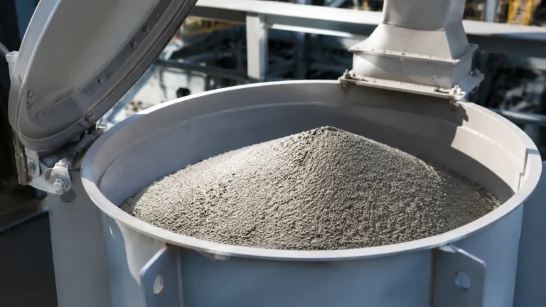
A: Yes, but the instrumentation choices will differ. While liquids provide a flat reflecting surface, solids (like powders or grains) often form cones or angles of repose. Radar sensors with a narrow beam angle (such as 80GHz models) are better suited for solids as they can target specific points on the uneven surface.
Q: What is the benefit of using an 80GHz radar over a 26GHz radar on my flowline?
A: The 80GHz radar has a much narrower beam angle. This allows it to avoid internal obstructions like ladders, pipes, or agitators that are common in complex industrial tanks. It also provides better performance in vessels with small mounting nozzles.
Q: How do I handle level measurement in a tank with steam?
A: Steam can cause condensation on the sensor face. For ultrasonic sensors, this often blocks the signal entirely. Radar sensors are much more resilient to steam, and many models include a specialized "dripping" antenna design that prevents water droplets from accumulating and interfering with the signal.
Conclusion
Developing a comprehensive flowline map is a vital step in ensuring the success of any industrial level measurement project. By understanding the principles of radar, ultrasonic, and hydrostatic technologies, and by accounting for the physical constraints of the installation site, engineers can build a reliable monitoring network. For those seeking to implement these solutions, the Main Page of Welk offers a deep dive into the specific instruments designed to meet the rigorous demands of modern industry. Proper mapping, combined with the right technology, results in a system that is not only accurate but also safe and cost-effective over the long term.