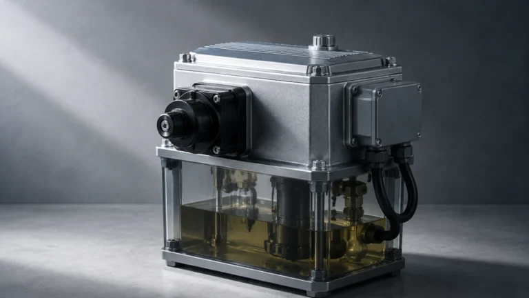
Liquid Level Gages
Liquid Level Gages
In the landscape of industrial process control, the ability to accurately monitor the contents of a vessel is fundamental to safety, efficiency, and inventory management. Liquid level gages are mechanical or electromechanical instruments designed to provide direct or indirect visual indication of the liquid height within a tank or pressure vessel. Unlike electronic transmitters that convert level data into a signal for a remote control room, liquid level gages often serve as the primary local reference point for operators on the plant floor.
As a professional manufacturer, Welk provides a diverse range of level measurement instruments, including radar, ultrasonic, and hydrostatic solutions. However, the traditional liquid level gage remains a cornerstone of industrial instrumentation due to its reliability and independence from power sources in many configurations. This guide explores the engineering principles, selection criteria, and practical applications of these essential devices.
Understanding Liquid Level Gage Principles
Before selecting an instrument, it is critical to understand the physics governing its operation. Liquid level gages generally operate based on three primary physical principles: the law of communicating vessels, magnetic coupling, or hydrostatic pressure.
The Law of Communicating Vessels
Most direct-reading liquid level gages, such as tubular, reflex, and transparent types, rely on the principle of communicating vessels. This principle states that in a set of interconnected containers, the liquid level will remain equal across all containers, provided the liquid is of uniform density and the pressure above the liquid is the same. By connecting a vertical chamber to the side of a process tank at both the top and bottom, the liquid rises in the gage to exactly the same height as the liquid in the tank. This allows for a direct visual measurement of the level.
Magnetic Coupling
Magnetic liquid level gages utilize a float containing an internal magnetic system. This float sits on top of the liquid inside a non-magnetic bypass chamber. As the liquid level changes, the float moves accordingly. Outside the chamber, a visual indicator—typically a series of bi-color flaps or a follower—is magnetically coupled to the float. As the float moves, the magnetic field flips the flaps or moves the follower, providing a clear visual representation of the level without the process fluid ever coming into contact with the viewing glass or the operator.
Light Refraction and Reflection
In glass-based gages, the visibility of the liquid interface is enhanced through optical principles. Reflex gages use a prism-shaped glass that relies on the difference in the refractive index between gas (vapor) and liquid. When light enters the glass, it is reflected back in the gas space (appearing silvery/bright) and absorbed in the liquid space (appearing dark). Transparent gages, conversely, use two parallel pieces of smooth glass to allow light to pass through the medium, which is essential for observing the color, clarity, or interface between two different liquids.
Common Types of Industrial Liquid Level Gages
Choosing the right gage requires matching the instrument type to the specific demands of the process fluid and environment.
1. Reflex Liquid Level Gages
Reflex gages are the most common choice for clean, non-viscous liquids. The inner surface of the glass has molded prismatic grooves.
- How it works: Light striking the grooves in the vapor space is reflected back to the observer, creating a bright silvery appearance. Light striking the grooves submerged in liquid is refracted into the liquid, making that section appear black.
- Best for: High-contrast viewing of clear liquids like water, solvents, and light hydrocarbons.
2. Transparent Liquid Level Gages
Transparent gages feature two heavy-duty plate glasses on opposite sides of the chamber.
- How it works: This design allows light to shine through the fluid from the back. It is often used with an illuminator for better visibility.
- Best for: Interface measurement (e.g., oil and water), dirty or viscous fluids, and applications requiring the observation of fluid color.
3. Magnetic Level Gages (MLGs)
Magnetic gages are increasingly preferred in hazardous or high-pressure environments where glass breakage poses a significant risk.
- How it works: A stainless steel or plastic chamber is mounted to the vessel. A magnetic float inside the chamber tracks the level, while an external rail of magnetic flags indicates the position.
- Best for: Toxic, corrosive, or high-pressure fluids. Because the chamber is a solid metal pipe, there is no risk of "glass blowouts."
4. Tubular Level Gages
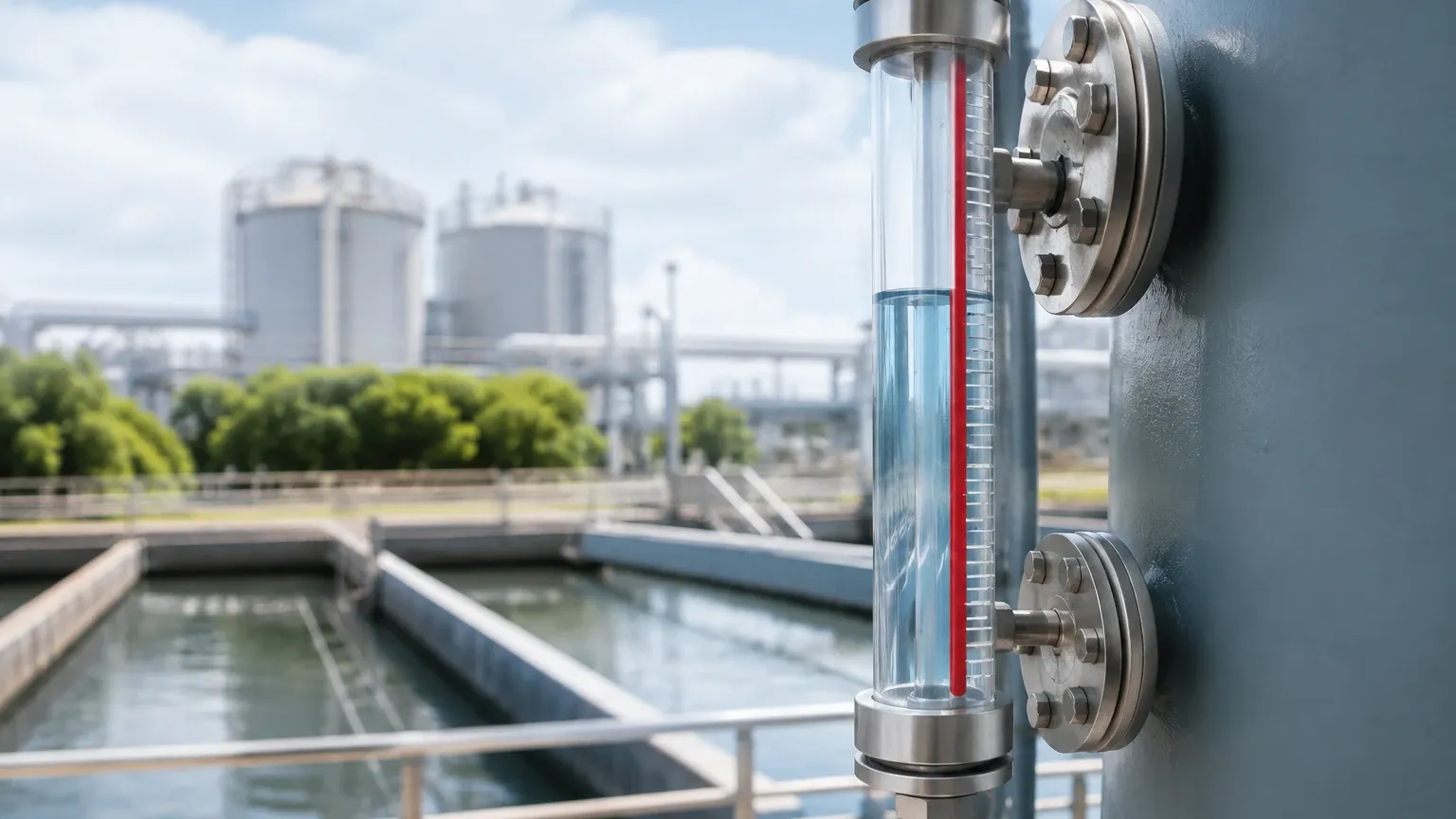
These are the simplest form of liquid level gages, consisting of a clear tube (usually glass or plastic) connected to the vessel via valves.
- How it works: Direct observation through the tube.
- Best for: Low-pressure, non-hazardous applications like water storage tanks or lubrication oil reservoirs.
Technical Selection Criteria for Process Applications
Selecting a liquid level gage involves more than just choosing a type; it requires a detailed analysis of the process conditions. Engineers should consult the Main Page of technical providers to ensure the chosen instrument meets the following criteria:
Pressure and Temperature Ratings
Every gage has a Maximum Allowable Working Pressure (MAWP) that decreases as temperature increases. For example, a reflex gage rated for 275 bar (4000 psi) at 38°C (100°F) might only be rated for 190 bar (2750 psi) at 315°C (600°F). It is vital to specify the maximum operating and design conditions during procurement.
Material Compatibility
The wetted parts—including the chamber, gaskets, and valves—must be chemically compatible with the process fluid. While 316 Stainless Steel is the standard for many applications, corrosive fluids may require Carbon Steel, Monel, Hastelloy, or PTFE lining. For magnetic gages, the float material is especially critical, as it must be light enough to float but strong enough to withstand the process pressure.
Specific Gravity (Density)
For magnetic level gages, the float must be engineered for the specific gravity (SG) of the liquid. A float designed for water (SG 1.0) will not work correctly in a light hydrocarbon with an SG of 0.6. If the SG varies significantly due to temperature changes, the gage accuracy may be affected.
Visibility and Length
The "visible length" is the actual range of the liquid that can be seen. For very tall tanks, multiple gage sections may be stacked (staggered) to provide continuous coverage over several meters.
Comparison Table: Liquid Level Gage Technologies
| Feature | Reflex Gages | Transparent Gages | Magnetic Gages | Tubular Gages |
| :— | :— | :— | :— | :— |
| Max Pressure | Up to 280 bar (4000 psi) | Up to 240 bar (3500 psi) | Up to 310 bar (4500 psi) | Low (< 10 bar) |
| Visibility | High (Black/Silver) | Moderate (Requires light) | Excellent (Colored flags) | High (Direct) |
| Interface Reading | No | Yes | Yes (Special float) | Yes |
| Hazardous Fluids | Moderate Risk | Moderate Risk | Safest (No glass) | High Risk |
| Maintenance | Glass cleaning/replacement | Glass cleaning/replacement | Minimal | Tube replacement |
Installation and Maintenance Best Practices
Correct installation is paramount to ensure the safety and longevity of liquid level gages.
Installation Considerations
1. Leveling: The gage must be installed perfectly vertical. Any tilt can cause the float in a magnetic gage to bind against the chamber walls or result in inaccurate readings in glass gages.
2. Isolation Valves: Always install high-quality isolation valves (offset valves are preferred) between the vessel and the gage. This allows for maintenance without draining the entire tank.
3. Safety Ball Checks: In glass gages, valves should be equipped with automatic ball checks. If the glass breaks, the sudden flow of fluid forces a stainless steel ball into a seat, sealing off the vessel and preventing a catastrophic leak.
4. Thermal Expansion: For high-temperature applications, ensure the mounting arrangement allows for the thermal expansion of the gage chamber to prevent stress on the process connections.
Maintenance Guidance
- Glass Inspection: For reflex and transparent gages, regularly check for "thinning" or clouding of the glass, especially in steam service. This is often a sign of chemical attack (glass erosion).
- Flushing: Periodically use the drain valve at the bottom of the gage to flush out sediment or scale that may have accumulated in the chamber.
- Gasket Replacement: Whenever a glass gage is disassembled, always use new gaskets and cushions. Reusing old gaskets is a common cause of leaks.
- Torque Sequences: When tightening the bolts on a glass gage cover, follow the manufacturer's specific torque sequence and values to ensure even pressure distribution across the glass.
Limitations and Risk Mitigation
While liquid level gages are robust, they have inherent limitations:
- Glass Fragility: In glass-based gages, there is always a risk of mechanical impact or thermal shock causing breakage. In critical areas, protective shields or magnetic gages should be used.
- Coating and Scaling: If the liquid leaves deposits (like wax or calcium), the glass will become obscured, or the magnetic float may become stuck. In these cases, non-contact methods like Welk’s radar level meters may be more appropriate.
- Boiling and Surging: If the liquid is boiling, the level in the gage may fluctuate or "bounce," making it difficult to read. Stilling wells or larger chamber diameters can help mitigate this.
Frequently Asked Questions (FAQs)
Q: Can I use a reflex gage for steam applications?
A: Yes, but with limitations. For high-pressure steam (above 20 bar / 300 psi), reflex glass can erode quickly. Transparent gages with mica shields are preferred for high-pressure steam service to protect the glass from the corrosive effects of the steam.
Q: How do I choose between a magnetic gage and a radar level meter?
A: A magnetic gage provides a local, visual indication and requires no power. A radar level meter provides high-accuracy digital data to a control system. Many modern plants use both: a magnetic gage for local reference and a radar sensor mounted on top of the magnetic gage chamber for remote monitoring.
Q: What is the purpose of a mica shield?
A: In transparent gages, a thin strip of mica is placed between the process fluid and the glass. This protects the glass from chemical attack by high-temperature alkaline solutions or steam, significantly extending the life of the glass.
Q: What happens if the specific gravity of my liquid changes?
A: For glass gages, the visual level remains accurate. For magnetic gages, a change in SG will change the buoyancy of the float. If the SG drops below the float's design limit, the float may sink, resulting in a false "low" reading.
Conclusion
Liquid level gages remain an indispensable tool for industrial process monitoring. By understanding the underlying principles of refraction and magnetic coupling, and by carefully evaluating process pressure, temperature, and fluid chemistry, engineers can select a solution that ensures both operational safety and accuracy. For those seeking a complete range of measurement technologies—from traditional liquid level gages to advanced ultrasonic and radar systems—visiting the Main Page provides access to technical specifications and expert support necessary for complex industrial applications.