Fluid Catalytic Cracking Unit
Fluid Catalytic Cracking Unit
The fluid catalytic cracking unit (FCCU) is often described as the "heart" of a modern oil refinery. Its primary function is to convert high-molecular-weight hydrocarbon fractions, such as heavy atmospheric gas oils and vacuum gas oils, into high-value products like gasoline, C3/C4 olefins, and light cycle oils. Because the process involves high temperatures, abrasive catalysts, and complex fluid dynamics, maintaining precise control over vessel levels is critical for both operational efficiency and plant safety.
In an environment where temperatures frequently exceed 700°C and pressures remain significant, level measurement instrumentation must be robust enough to withstand mechanical erosion and thermal stress. This article examines the technical requirements for level monitoring within the fluid catalytic cracking unit and provides an engineering perspective on selecting the appropriate measurement technologies.
Measurement Principles for FCCU Level Control
Before selecting specific instruments for a fluid catalytic cracking unit, it is essential to understand the underlying physics of the measurement technologies commonly employed in these sections of the refinery.
Radar Level Measurement (Time of Flight)
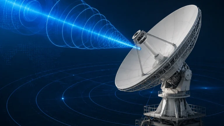
Radar level meters operate on the Time of Flight (ToF) principle. The device emits high-frequency electromagnetic pulses (typically in the 26GHz or 80GHz range). These pulses travel at the speed of light, reflect off the surface of the medium (whether liquid or solid catalyst), and return to the sensor. The distance is calculated based on the time delay between transmission and reception.
In an FCCU, non-contact radar is often preferred because it does not require physical contact with abrasive catalyst particles. 80GHz radar, in particular, offers a narrow beam angle, which is advantageous when measuring levels through narrow nozzles or in vessels with internal obstructions like cyclones or steam coils.
Magnetic Level Gauges (Buoyancy and Magnetism)
Magnetic level gauges utilize a float containing a high-strength magnet. This float moves up and down within a bypass chamber (standpipe) connected to the process vessel. As the float moves, it toggles magnetic flaps or a follower on an external scale, providing a visual indication of the level. This technology is purely mechanical and does not require power for the local display, making it a reliable secondary check for primary electronic sensors.
Hydrostatic Level Transmitters (Pressure Differential)
Hydrostatic measurement relies on the relationship between the height of a liquid column and the pressure it exerts at the base of the vessel. By measuring the head pressure and compensating for the vapor space pressure (using a differential pressure setup), the level can be inferred. In the fluid catalytic cracking unit, this is frequently used in the fractionator bottoms or auxiliary water-wash vessels.
Key Process Areas in the Fluid Catalytic Cracking Unit
The fluid catalytic cracking unit is comprised of several distinct sections, each presenting unique challenges for level instrumentation.
1. The Reactor and Regenerator Loop
The core of the FCCU is the reactor-regenerator loop. Here, the catalyst is continuously circulated between two large vessels. In the reactor, the heavy oil feed meets the hot catalyst, and the cracking reaction occurs. The catalyst becomes "spent" as coke deposits on its surface. It then flows to the regenerator, where the coke is burned off in the presence of air.
Level control in the regenerator is vital to maintain the catalyst inventory and ensure proper residence time for carbon burnout. Measuring the level of the catalyst bed is challenging because the catalyst is "fluidized" with air, creating a density gradient rather than a sharp interface. High-frequency radar is often used here, though it must be equipped with specialized cooling jackets and purging systems to protect the electronics from extreme heat.
2. The Main Fractionator
After the cracking reaction, the hydrocarbon vapors enter the main fractionator. This tower separates the products into various boiling point fractions. The level at the bottom of the fractionator (the slurry or bottom oil) must be monitored closely to prevent pump cavitation and to ensure that the heavy cycle oil is properly recycled or sent to storage. Because this medium is often viscous and contains residual catalyst fines, non-contact radar or high-temperature magnetic level gauges are the preferred solutions.
3. Catalyst Hoppers and Storage
Fresh and spent catalyst is stored in large hoppers. These silos require level monitoring to manage inventory and ensure a continuous supply to the unit. Since the catalyst is a dry, abrasive powder, 80GHz radar is highly effective here, as the short wavelength allows for better reflection off the sloped surface of the powder heap.
Technical Challenges: Temperature, Abrasion, and Turbulence
Designing level systems for a fluid catalytic cracking unit requires addressing three primary environmental factors:
* Extreme Temperatures: Process temperatures in the regenerator can reach 700°C to 760°C (approx. 1300°F to 1400°F). Standard level sensors cannot withstand these conditions directly. Instruments must be installed with thermal offsets, cooling fins, or specialized wave-guide extensions to keep the electronic components within their operating temperature range (typically below 80°C).
* Catalyst Abrasion: The catalyst used in the FCCU is typically a fine zeolite powder. When moving at high velocities, it acts like sandpaper, quickly eroding internal probes or glass windows. For this reason, non-contact measurement is generally superior to contact-based methods like guided wave radar (GWR) in high-velocity zones.
* Vapor Space Complexity: The atmosphere inside an FCCU vessel is often filled with steam, hydrocarbon vapors, and suspended catalyst dust. These can attenuate radar signals. Selecting a radar meter with a high dynamic range and advanced signal processing algorithms is necessary to filter out noise and identify the true material surface.
Selection Table for FCCU Level Instruments
The following table provides a general guideline for selecting level technologies based on the specific application within the fluid catalytic cracking unit.
| Application | Recommended Technology | Key Benefit | Limitation |
| :— | :— | :— | :— |
| Regenerator Bed | 80GHz Radar (Non-contact) | High precision, no contact with hot catalyst | Requires air/nitrogen purging for cooling |
| Fractionator Bottoms | Magnetic Level Gauge | Visual redundancy, robust for viscous fluids | Limited to bypass installation |
| Catalyst Storage Silo | 80GHz Radar | Excellent performance on solids/powders | Dust may require periodic lens cleaning |
| Separator Vessels | Guided Wave Radar (GWR) | Handles interface measurement (oil/water) | Probes can be coated by heavy oils |
| Steam Drums | Hydrostatic / DP | Proven reliability for high-pressure water | Density changes with temperature |
For engineers looking to integrate these technologies into their facility, reviewing comprehensive product specifications is the first step toward a successful installation. You may Review product options and application support at the Welk Main Page to find specific hardware configurations suitable for high-temperature refining environments.

Installation and Maintenance Considerations
Correct installation is as important as instrument selection in a fluid catalytic cracking unit. Failure to follow engineering best practices can lead to premature instrument failure or inaccurate readings.
Nozzle Design and Placement
For radar installations, the nozzle should be perpendicular to the product surface. In catalyst hoppers, the sensor should be positioned away from the fill stream to avoid signal interference. For magnetic level gauges, the bypass chamber must be perfectly vertical to ensure the float moves freely without sticking due to friction or sediment buildup.
Purging and Cooling
In high-temperature zones, nitrogen or instrument air purging is used for two reasons: to cool the sensor face and to prevent catalyst dust from accumulating on the antenna or lens. A continuous purge flow is often required, and the system should include a flow meter and a check valve to prevent process gases from back-flowing into the air header.
Calibration and Verification
Level instruments in the FCCU should be calibrated during the initial commissioning phase. For radar units, this involves setting the "Zero" and "Full" points and performing a "mapping" of the vessel to ignore internal obstructions like ladders or agitators. Regular verification against a secondary source, such as a manual dip or a magnetic gauge, is recommended every 6 to 12 months.
Frequently Asked Questions (FAQ)
Q: Why is 80GHz radar preferred over 26GHz for catalyst measurement?
A: 80GHz radar has a much smaller wavelength, which results in a more focused beam. This allows the signal to pass through narrow nozzles more easily and provides a stronger reflection from the fine, porous surface of the catalyst powder.
Q: Can ultrasonic sensors be used in the fluid catalytic cracking unit?
A: Ultrasonic sensors are generally not suitable for the reactor or regenerator due to the high temperatures and the vacuum/pressure conditions, which affect the speed of sound. However, they are excellent for auxiliary applications like wastewater sumps or chemical storage tanks located in the refinery's off-site areas.
Q: How do you handle "foaming" in the fractionator?
A: Foaming can absorb radar signals, leading to a "loss of echo." In applications where foaming is expected, choosing a radar with high sensitivity and using a stilling well can help stabilize the surface and provide a more reliable reading.
Q: What is the lifespan of a level sensor in an FCCU?
A: With proper purging and thermal protection, a high-quality radar sensor can last 5 to 10 years. Without protection, the electronics can fail within months due to thermal degradation.
Conclusion
Effective level management within the fluid catalytic cracking unit is a balance of selecting the right technology and implementing rigorous installation standards. Whether managing the catalyst inventory in the regenerator or monitoring the slurry level in the main fractionator, the reliability of these measurements directly impacts the refinery's bottom line. By utilizing advanced radar and magnetic measurement solutions, operators can ensure the safety and longevity of one of the most critical units in the hydrocarbon processing industry.