Fuel Level Sensors
Fuel Level Sensors
In industrial environments, the precise monitoring of fuel levels is a critical operational requirement. Whether managing diesel for backup generators, kerosene for heating, or specialized aviation fuels, accurate measurement ensures process continuity, prevents environmental hazards, and optimizes inventory management. Fuel level sensors serve as the primary interface between the physical storage tank and the control system, converting liquid height or volume into readable data.
Selecting the appropriate technology requires a deep understanding of the physical properties of the fuel, the geometry of the storage vessel, and the environmental conditions of the installation site. This guide examines the primary measurement principles, selection criteria, and installation best practices for industrial fuel level monitoring.
Measurement Principles for Fuel Level Sensors
Before selecting a sensor, it is essential to understand the underlying physics of how different technologies detect liquid levels. Fuel level sensors generally fall into two categories: contact and non-contact.
1. Hydrostatic Pressure Measurement
Hydrostatic level transmitters operate on the principle that the pressure at the bottom of a tank is directly proportional to the height of the liquid column above it. The relationship is defined by the formula: $P = \rho \times g \times h$, where $P$ is pressure, $\rho$ is the density of the fuel, $g$ is gravity, and $h$ is the height of the liquid.
In this application, a submersible pressure transducer is lowered to the bottom of the tank. It measures the "head pressure" of the fuel. Because fuels like diesel or gasoline have lower densities than water, the sensor must be calibrated to the specific gravity of the fuel to provide an accurate level reading. This method is highly effective for deep underground storage tanks (USTs) and large atmospheric tanks.
2. Ultrasonic (Non-Contact)
Ultrasonic sensors emit high-frequency sound pulses that travel through the air, reflect off the fuel surface, and return to the sensor. The device calculates the distance based on the "time-of-flight" of the sound wave.
Since the speed of sound is affected by air temperature, most high-quality ultrasonic sensors include integrated temperature compensation. However, ultrasonic waves can be scattered by heavy vapors or foam on the fuel surface, which may occur during high-flow filling operations. They are best suited for stable, vented tanks where the sensor does not come into contact with the corrosive or volatile properties of the fuel.
3. Radar Level Measurement
Radar sensors use electromagnetic waves rather than sound waves. There are two primary types used in fuel applications:
* Non-Contact Radar: Emits microwave pulses (typically at 26 GHz or 80 GHz). These waves are unaffected by temperature shifts, vacuum, or high pressure. They are ideal for volatile fuels that produce heavy vapors, as microwaves pass through gas layers without interference.
* Guided Wave Radar (GWR): Uses a physical probe (cable or rod) to guide the microwave signal to the fuel surface. GWR is particularly effective for fuels with low dielectric constants, as the concentrated energy along the probe provides a stronger return signal than non-contact radar in some scenarios.
4. Capacitance Measurement
Capacitive fuel level sensors treat the tank and the sensor probe as two plates of a capacitor, with the fuel acting as the dielectric material. As the fuel level rises, the total capacitance of the system changes because the dielectric constant of fuel (typically around 2.0 to 2.2) is different from that of air (1.0). This change is converted into a linear level signal. These sensors are robust and have no moving parts, making them popular for vehicle fuel tanks and smaller industrial day tanks.
5. Magnetic Level Gauges and Switches
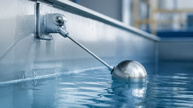
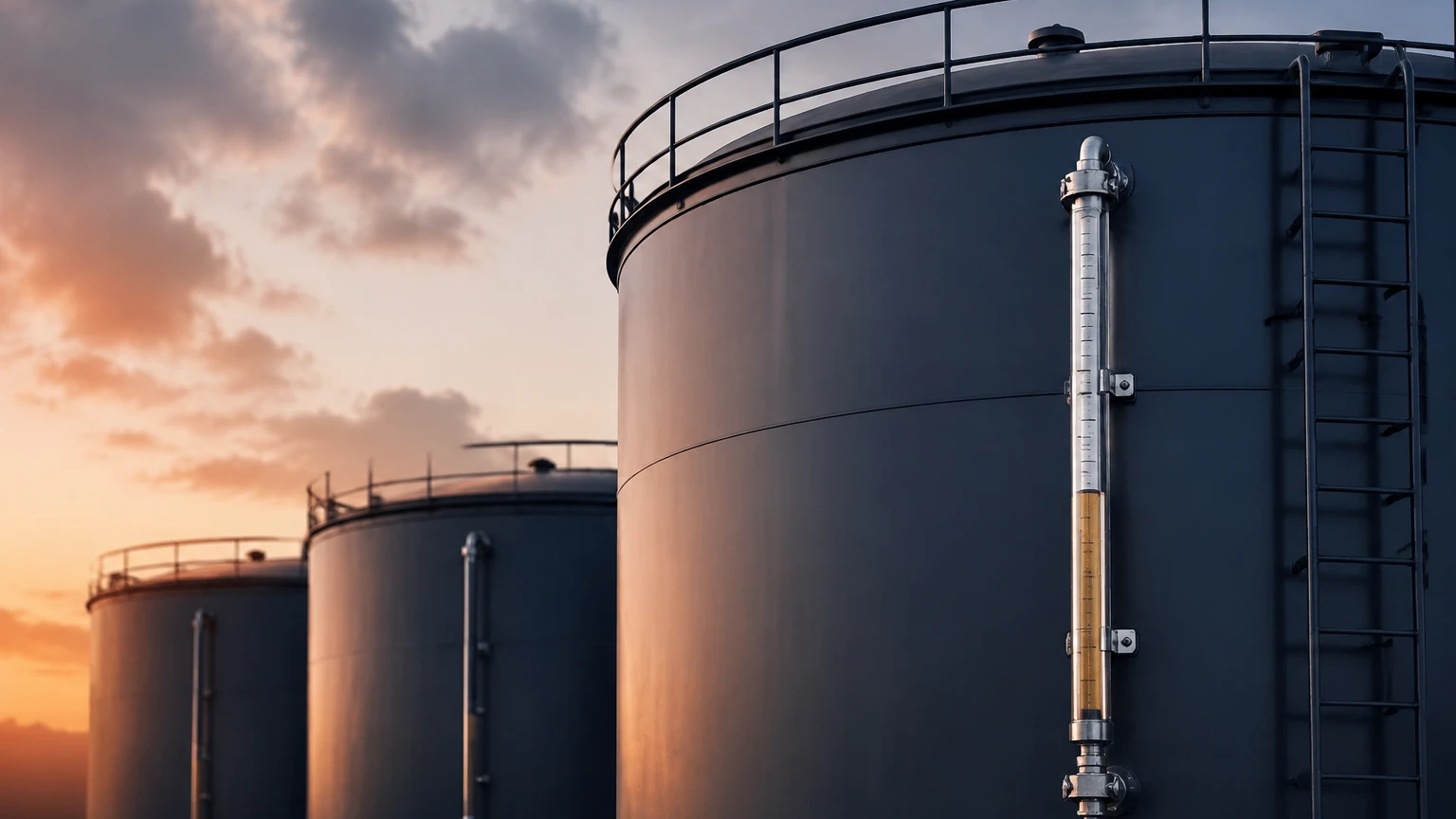
Magnetic level gauges utilize a float containing an internal magnet that moves with the fuel level. This float interacts with an external indicator or a series of reed switches (magnetostrictive) located outside the chamber. This provides a clear visual indication and a highly accurate electronic signal. Because the electronics are isolated from the fuel, this is a very safe method for flammable liquids.
Selection Criteria for Industrial Fuel Applications
Choosing the right sensor involves balancing accuracy requirements, budget, and the physical constraints of the application. For a comprehensive overview of available technologies and technical specifications, engineers should consult the Main Page of the Welk product catalog.
Key Evaluation Factors
| Feature | Hydrostatic | Ultrasonic | Radar (Non-Contact) | Capacitance |
| :— | :— | :— | :— | :— |
| Accuracy | High (0.1% to 0.5%) | Moderate (0.25%) | Excellent (±2mm) | Moderate to High |
| Contact | Yes (Submerged) | No | No | Yes (Probe) |
| Vapor Sensitivity | None | High | None | None |
| Installation | Bottom/Top | Top | Top | Top |
| Typical Range | 1m – 200m | 0.3m – 15m | 0.3m – 30m+ | 0.1m – 5m |
| Cost | Low to Mid | Mid | Mid to High | Mid |
Fuel Characteristics
* Dielectric Constant: If using Radar or Capacitance, the dielectric constant ($ε_r$) of the fuel is vital. Standard diesel has a low $ε_r$, which may require high-frequency radar (80 GHz) or Guided Wave Radar for a reliable signal.
* Viscosity and Sediment: Heavy fuel oils (HFO) may coat contact-based probes. In these cases, non-contact radar is preferred to prevent maintenance issues caused by paraffin or bitumen buildup.
* Flammability: Fuel tanks are often classified as hazardous areas (Zone 0, 1, or 2). Sensors must carry appropriate certifications such as ATEX, IECEx, or UL/CSA intrinsically safe ratings.
Installation Considerations and Best Practices
Proper installation is as important as sensor selection. Even the most advanced radar level meter will fail if placed incorrectly.
1. Avoiding Obstructions: For ultrasonic and radar sensors, the "beam angle" must be considered. Sensors should not be installed near the tank wall or close to internal structures like ladders, heating coils, or agitators, as these will create "false echoes."
2. Stilling Wells: In tanks where fuel is frequently pumped in and out, turbulence and surface ripples can cause erratic readings. Installing the sensor inside a stilling well (a vertical pipe with vent holes) provides a calm surface for the sensor to measure.
3. Nozzle Height: For top-mounted sensors, the mounting nozzle should be as short as possible. If the nozzle is too long, it can create internal reflections that interfere with the sensor's ability to detect the fuel level when the tank is nearly full (the "dead zone").
4. Venting: Hydrostatic sensors require a vented cable to compensate for changes in atmospheric pressure. If the vent tube is blocked or crimped, the sensor will show an offset error.
Limitations and Common Risks
While modern sensors are highly reliable, certain conditions can compromise performance:
* Temperature-Induced Density Changes: Hydrostatic sensors measure mass/pressure. If the fuel temperature rises significantly, the fuel expands and its density decreases. The pressure at the bottom remains the same, but the actual volume/height has increased. If volume accuracy is critical, temperature compensation must be integrated into the control logic.
* Condensation: In outdoor tanks, temperature swings can cause water to condense on the face of ultrasonic or radar transducers. While radar is less affected, a heavy buildup of water droplets on an ultrasonic transducer can attenuate the signal. Many Welk sensors feature drip-off lens designs to mitigate this.
* Tank Geometry: Non-linear tanks (such as horizontal cylindrical tanks or tanks with conical bottoms) require a strapping table or "tank strapping" in the transmitter software to convert level (mm) into volume (liters).
Frequently Asked Questions (FAQ)
Q: Can I use the same sensor for diesel and gasoline?
A: Generally, yes, but the sensor must be rated for the specific hazardous zone. Gasoline is more volatile and has a different specific gravity and dielectric constant than diesel. If using a hydrostatic or capacitance sensor, the device must be recalibrated for the change in fluid properties.
Q: How do I handle foam during high-speed filling?
A: Foam is a challenge for ultrasonic sensors because it absorbs sound waves. Radar (especially 80 GHz) or Guided Wave Radar is the better choice for foaming applications, as the signal can penetrate the foam to reach the liquid surface.
Q: What is the typical maintenance schedule for fuel level sensors?
A: Non-contact sensors (Radar/Ultrasonic) require very little maintenance, often only a yearly visual inspection. Contact sensors (Hydrostatic/Capacitance) should be checked every 6 to 12 months for buildup or corrosion, especially if the fuel contains additives or contaminants.
Q: How does the dielectric constant affect radar measurement?
A: The dielectric constant determines how much of the radar energy is reflected back to the sensor. Fuels have low dielectric constants (2.0–2.2), meaning they reflect less energy than water (80). Modern high-sensitivity radar modules are designed specifically to handle these low-reflective surfaces reliably.
Conclusion
Effective fuel management starts with selecting a level measurement technology that aligns with the specific physical and environmental demands of the application. Hydrostatic sensors offer a cost-effective solution for deep storage, while radar provides the highest precision for volatile and complex environments. By considering factors such as dielectric constants, tank geometry, and hazardous area requirements, engineers can ensure long-term accuracy and safety.
For technical assistance in selecting the right instrumentation for your project, or to review detailed product data sheets, visit the Main Page to explore the full range of industrial level measurement solutions.