Fuel Oil Flow Meter
Fuel Oil Flow Meter
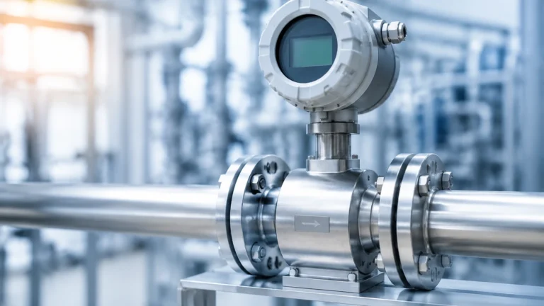
In industrial combustion systems, power generation, and marine engineering, the precise measurement of fuel consumption is critical for operational efficiency, cost accounting, and environmental compliance. A fuel oil flow meter is a specialized instrument designed to quantify the volume or mass of liquid fuels—ranging from light distillates like diesel and kerosene to heavy residual oils (HFO)—as they move through a piping system.
Selecting the correct flow meter requires a deep understanding of fluid dynamics, particularly how viscosity changes with temperature, and how different measurement technologies interact with the physical properties of various fuel types. This guide provides a technical overview of fuel oil flow measurement principles, selection criteria, and installation best practices for engineering professionals.
Measurement Principles for Fuel Oil
Before selecting a specific device, it is essential to understand the physical principles used to derive flow data. Fuel oils present unique challenges, such as high viscosity and the potential for entrained air or solid contaminants.
Positive Displacement (PD)
Positive displacement meters are among the most common choices for fuel oil. They operate by capturing a fixed volume of fluid in a chamber and then moving it through the meter. Common types include oval gear, oscillating piston, and screw meters.
- Principle: As the fuel flows, it rotates internal gears or pistons. Each rotation corresponds to a specific volume of fluid.
- Suitability: Excellent for high-viscosity fluids like heavy fuel oil. Their accuracy actually improves as viscosity increases because the fluid forms a better seal between the moving parts.
Coriolis Mass Flow
Coriolis meters measure the mass of the fuel directly rather than its volume. This is particularly useful for fuel oil because the density of fuel changes significantly with temperature.
- Principle: The fluid passes through a vibrating tube. The mass flow causes a phase shift in the vibration (the Coriolis effect), which is measured by sensors.
- Suitability: Ideal for high-precision applications and custody transfer. They also provide density and temperature data simultaneously.
Turbine Flow Meters
Turbine meters use a multi-bladed rotor suspended in the fluid stream.
- Principle: The velocity of the fuel turns the rotor; the rotational speed is proportional to the flow rate.
- Suitability: Best for low-viscosity fuels like diesel or light gas oil. They are sensitive to viscosity changes, which can affect the calibration factor (K-factor).
Ultrasonic (Transit-Time)
Ultrasonic meters use sound waves to determine flow velocity.
- Principle: Transducers send pulses through the fluid. The difference in time between pulses traveling with the flow versus against the flow is used to calculate velocity.
- Suitability: Non-intrusive (clamp-on) versions are useful for temporary measurements or where cutting into the pipe is not feasible. However, they require clean fluids and may struggle with heavy oils containing high levels of particulates.
Key Evaluation Criteria
Choosing a fuel oil flow meter involves balancing accuracy requirements against the physical constraints of the application. The following table summarizes the performance characteristics of the primary technologies.
Selection Comparison Table
| Technology | Accuracy (Typical) | Viscosity Range | Pressure Drop | Maintenance | Best Use Case |
| :— | :— | :— | :— | :— | :— |
| Oval Gear (PD) | ±0.5% of Rate | High (up to 50,000 cP) | Medium | Moderate | Heavy Fuel Oil (HFO), Lubricants |
| Coriolis | ±0.1% to 0.2% | Very High | Low to Medium | Low | Custody Transfer, Mass Balance |
| Turbine | ±0.25% to 0.5% | Low (< 20 cSt) | Medium | High | Diesel, Kerosene, Light Distillates |
| Variable Area | ±2.0% to 5.0% | Low to Medium | Low | Low | Visual Monitoring, Burner Feeds |
| Ultrasonic | ±1.0% to 2.0% | Medium | None | Very Low | Retrofitting, Non-conductive fluids |
Factors Influencing Performance
Viscosity and Temperature
Viscosity is the most significant variable in fuel oil measurement. For instance, Heavy Fuel Oil (HFO) must be heated to approximately 100°C to 150°C to reduce its viscosity enough for pumping and atomization. A flow meter calibrated for diesel at 20°C will not provide accurate readings for HFO at 120°C unless it is a mass flow meter or has sophisticated viscosity compensation.
Pressure and Pulsation
Fuel systems using reciprocating pumps (like many diesel engines) create pressure pulsations. These pulses can cause mechanical wear in PD meters or "noise" in electronic meters. Dampeners or specific meter orientations may be required to mitigate these effects.
Contamination and Filtration
Fuel oils often contain particulates, carbon deposits, or metallic traces. Positive displacement and turbine meters have tight internal clearances. Without a strainer (typically 40 to 100 mesh) installed upstream, these particles can jam or erode the internal components, leading to premature failure.
Installation Considerations
Proper installation is as important as the technology selection itself. Even the most expensive Coriolis meter will fail to perform if installed incorrectly.
1. Straight Pipe Runs: Most velocity-based meters (Turbine, Ultrasonic) require a specific length of straight pipe upstream (typically 10D to 20D) and downstream (5D) to ensure a stable flow profile. PD meters are generally less sensitive to flow profiles but still benefit from stable piping.
2. Air and Gas Elimination: If air is trapped in the fuel line (common after filter changes or tank switching), the flow meter will measure the air as fuel, leading to significant over-reading. An air eliminator should be installed at the highest point before the meter.
3. Orientation: Most meters can be installed horizontally or vertically. However, in vertical installations, the flow should always be upward to ensure the pipe remains full of liquid and to prevent air pockets from forming.
4. Bypass Lines: For critical systems, a bypass manifold with isolation valves allows for meter maintenance or calibration without shutting down the entire fuel supply to the boiler or engine.
Integration with Level Measurement
In a comprehensive fuel management system, flow meters do not work in isolation. While a fuel oil flow meter tracks consumption at the burner or engine, level measurement instruments monitor the inventory in the bulk storage tanks. Comparing the volume delivered (measured by tank level) against the volume consumed (measured by flow meters) allows operators to detect leaks, verify delivery quantities, and calculate burner efficiency.
For engineers designing these integrated systems, selecting reliable level transmitters is a necessary parallel task. For a wide range of industrial level measurement solutions that complement flow monitoring, you can Review product options and application support to ensure your storage tanks are as precisely monitored as your flow lines.
Common Risks and Limitations
- Cavitation: If the pressure drop across the meter is too high, the fuel may reach its vapor pressure, causing bubbles to form. This damages the meter and ruins accuracy.
- Over-speeding: Operating a meter beyond its rated maximum flow rate, even for short periods, can cause catastrophic mechanical failure, especially in turbine and PD types.
- Thermal Expansion: If a meter is isolated between two closed valves while the fuel is heated, the resulting thermal expansion can generate extreme pressures, potentially rupturing the meter housing.
Frequently Asked Questions (FAQ)
1. How often should a fuel oil flow meter be calibrated?
For internal process monitoring, annual calibration is standard. For custody transfer (where money changes hands based on the reading), local regulations often mandate calibration every six months or after a specific volume has passed through the meter.
2. Can I use a water flow meter for fuel oil?
Generally, no. Water meters are often made of materials (like certain rubbers or plastics) that degrade when exposed to hydrocarbons. Furthermore, the calibration for water (viscosity of 1 cP) is entirely different from fuel oil.
3. Why is my flow meter reading higher than the actual consumption?
The most common cause is entrained air or gas in the line. Since the meter measures volume, it cannot distinguish between liquid fuel and air bubbles. Installing an air separator is the standard solution.
4. What is the difference between "Pulse Output" and "4-20mA"?
A pulse output sends a signal for every unit of volume (e.g., 1 pulse per liter), which is ideal for totalizing fuel use over time. A 4-20mA signal represents the instantaneous flow rate (e.g., 4mA = 0 L/h, 20mA = 1000 L/h), which is used for real-time control and monitoring.
5. Does the sulfur content in fuel affect the meter?
High-sulfur fuels can be corrosive to certain metals. When selecting a meter for HFO or crude oil, ensure the wetted parts (the parts touching the fuel) are made of compatible materials like 316 stainless steel or specifically treated alloys.
Conclusion
Effective fuel management starts with the selection of a flow meter that matches the specific physical properties of the fuel and the operational demands of the environment. While Positive Displacement meters remain the workhorse for heavy oils due to their robustness and viscosity handling, Coriolis meters are increasingly favored for high-value applications where mass-based accuracy is paramount. By adhering to strict installation standards—including filtration and air elimination—and integrating flow data with reliable tank level monitoring, industrial facilities can achieve optimal fuel efficiency and rigorous cost control.