Gage Pressure Transducer
Gage Pressure Transducer
In the field of industrial instrumentation, the gage pressure transducer serves as a fundamental component for monitoring process pressures and determining liquid levels in tanks and vessels. Unlike absolute pressure sensors, which measure pressure relative to a perfect vacuum, a gage pressure transducer measures pressure in relation to the local atmospheric pressure. This distinction is critical in many engineering applications where the atmospheric pressure acts on both the sensor and the process, effectively canceling out barometric fluctuations.
For engineers and facility managers, understanding the nuances of how these devices operate, their integration into hydrostatic level measurement systems, and the criteria for selecting the correct hardware is essential for ensuring process safety and accuracy. This guide provides a technical overview of gage pressure transducers, their principles of operation, and practical considerations for industrial implementation.
Measurement Principles of Gage Pressure Transducers
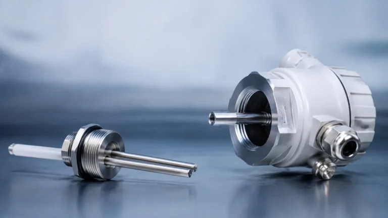
The core function of a gage pressure transducer is to convert mechanical force into a measurable electrical signal. This conversion typically occurs through the deflection of a sensing diaphragm. To measure "gage" pressure, one side of this diaphragm is exposed to the process media, while the other side is vented to the atmosphere.
Piezoresistive Sensing Technology
Piezoresistive transducers are among the most common types used in industrial level measurement. They utilize a silicon or metallic diaphragm with integrated strain gages. When pressure is applied, the diaphragm deforms, causing a change in the electrical resistance of the strain gages. This change is measured using a Wheatstone bridge circuit. Because silicon has a high gage factor, these sensors offer excellent sensitivity and resolution.
Ceramic Capacitive Sensing
In applications involving corrosive chemicals or abrasive slurries, ceramic capacitive sensors are often preferred. These consist of a ceramic base and a moving diaphragm that form a capacitor. As pressure moves the diaphragm closer to the base, the capacitance changes. Ceramic is naturally resistant to many aggressive media and provides high structural stability, making it ideal for long-term installations in harsh environments.
The Importance of Venting
For a transducer to provide a true gage reading, the reference side of the sensing element must remain at atmospheric pressure. In submersible applications, this is achieved through a specialized cable containing a small vent tube. This tube runs the length of the cable to a junction box or controller that is open to the atmosphere. If this vent becomes blocked or moisture enters the tube, the sensor will produce inaccurate readings as the internal reference pressure deviates from the actual ambient pressure.
Application in Hydrostatic Level Measurement
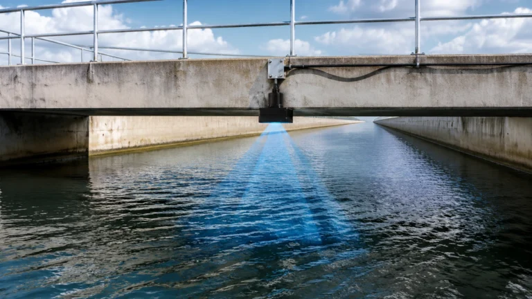
One of the primary uses for a gage pressure transducer in B2B industrial sectors is hydrostatic level measurement. This method relies on the principle that the pressure at the bottom of a liquid column is directly proportional to the height of that liquid and its specific gravity.
The mathematical relationship is defined as:
P = ρ × g × h
Where:
* P is the hydrostatic pressure (measured by the transducer).
* ρ (Rho) is the density of the liquid.
* g is the acceleration due to gravity (approximately 9.81 m/s²).
* h is the height of the liquid column.
Because a gage pressure transducer automatically subtracts the atmospheric pressure pressing down on the surface of an open tank, the resulting signal represents only the pressure exerted by the liquid itself. This makes it a cost-effective and reliable solution for water treatment, chemical storage, and fuel tank monitoring. For a comprehensive look at various measurement technologies, you can Review product options and application support to see how gage pressure units compare to radar or ultrasonic alternatives.
Technical Selection Criteria
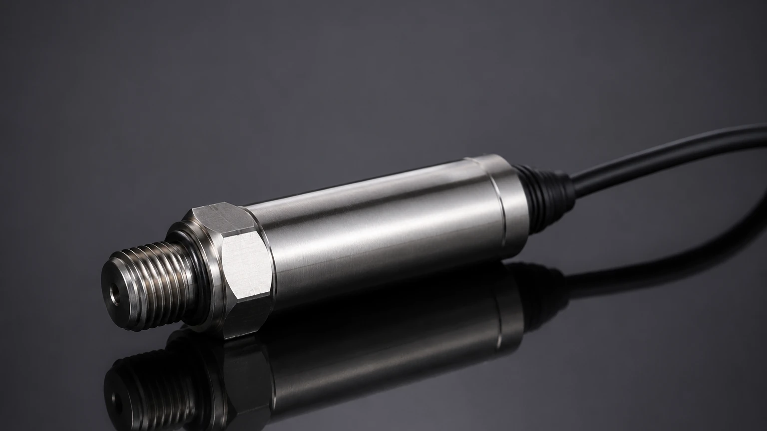
Selecting the right gage pressure transducer requires a detailed analysis of the process conditions. Failure to account for chemical compatibility or pressure spikes can lead to premature sensor failure.
Pressure Range and Overpressure Ratings
It is standard practice to select a transducer with a range approximately 25% to 50% higher than the maximum expected process pressure. This provides a safety margin for unexpected surges. Engineers must also check the "overpressure limit"—the maximum pressure the sensor can withstand without permanent damage to the calibration—and the "burst pressure," which is the point of mechanical failure.
Wetted Materials
The materials in contact with the process (the wetted parts) must be chemically compatible with the media. Common options include:
* 316L Stainless Steel: The standard for water and mild chemicals.
* Hastelloy C: Required for highly corrosive acids or seawater.
* PTFE/Teflon Coatings: Used to prevent adhesion in viscous or sticky fluids.
Signal Output and Communication
In modern industrial automation, the 4-20 mA current loop remains the industry standard due to its resistance to electrical noise over long cable runs. However, digital protocols such as Modbus RTU or HART are increasingly common, allowing for remote diagnostics and the transmission of secondary variables like process temperature.
Selection Comparison Table
| Feature | Piezoresistive (Stainless) | Ceramic Capacitive | Submersible Hydrostatic |
| :— | :— | :— | :— |
| Best Use Case | General oil/gas, hydraulics | Corrosive chemicals, slurries | Deep wells, water reservoirs |
| Accuracy | High (up to 0.1% FS) | Moderate (0.2% – 0.5% FS) | High (0.1% – 0.25% FS) |
| Durability | Good | Excellent (chemical resist) | High (IP68 rated) |
| Reference | Vented to atmosphere | Vented to atmosphere | Vented via cable tube |
| Typical Output | 4-20mA, 0-10V, Modbus | 4-20mA, HART | 4-20mA |
Installation Considerations and Best Practices
Proper installation is as important as sensor selection. Even the most accurate gage pressure transducer will provide poor data if installed incorrectly.
1. Avoid Turbulence: In tanks with agitators or high-velocity inlet flows, the transducer should be installed in a stilling well. This protects the diaphragm from mechanical stress and prevents "noise" in the pressure signal caused by moving liquid.
2. Mounting Location: For level measurement, the sensor should be located as close to the bottom of the tank as possible. However, it should be mounted slightly above the very bottom to avoid the accumulation of sediment or sludge that could clog the pressure port.
3. Moisture Protection: For vented cables, always use a desiccant cartridge or a specialized vent filter at the atmospheric end of the tube. This prevents water vapor from condensing inside the tube, which could lead to sensor drift or internal corrosion.
4. Electrical Grounding: Ensure the transducer housing is properly grounded, especially in outdoor installations prone to lightning strikes or in environments with heavy electrical machinery that generates EMI (Electromagnetic Interference).
Limitations and Environmental Factors
While highly versatile, gage pressure transducers have specific limitations that must be managed:
* Temperature Sensitivity: Pressure sensors are affected by temperature changes, which can cause the diaphragm material to expand or contract. High-quality transducers include internal temperature compensation circuits to minimize this error, but extreme temperatures may still require remote mounting via a capillary tube or cooling siphon.
* Atmospheric Blockage: If the vent port is sealed (e.g., by paint or debris), the sensor effectively becomes a sealed gage sensor. This means it will no longer compensate for barometric changes, leading to errors. For example, a significant storm system could cause a level reading error of several centimeters if the sensor is not properly vented.
* Vacuum Risks: Standard gage pressure transducers are designed for positive pressure. If a vacuum occurs in the tank (due to rapid emptying or cooling), it may pull the diaphragm in the opposite direction, potentially damaging sensors not rated for vacuum service.
Frequently Asked Questions (FAQ)
Q: What is the difference between a gage pressure transducer and a differential pressure (DP) transmitter?
A: A gage pressure transducer has one process connection and is vented to the atmosphere. A DP transmitter has two process connections and measures the difference between them. DP transmitters are typically used for level measurement in pressurized (closed) tanks, whereas gage transducers are used for vented (open) tanks.
Q: Can I use a gage pressure transducer for steam applications?
A: Yes, but a pigtail siphon or water seal must be used to prevent live steam from contacting the sensor diaphragm directly, as the high temperature can damage the electronics and sensing element.
Q: How often should a gage pressure transducer be calibrated?
A: For most industrial applications, an annual calibration check is recommended. However, in critical safety applications or harsh environments with high pressure cycling, semi-annual calibration may be necessary to account for potential sensor drift.
Q: Does the length of the cable affect the accuracy of a 4-20mA transducer?
A: Generally, no. One of the advantages of a 4-20mA current loop is that the signal remains constant regardless of the resistance in the wire, provided the power supply voltage is sufficient to overcome the total loop impedance. This allows for cable runs of hundreds of meters without signal degradation.
By carefully evaluating the process media, pressure requirements, and environmental conditions, B2B procurement and engineering teams can select a gage pressure transducer that provides reliable service for years. For further technical specifications and to explore specific models tailored to your industry, refer to the Main Page for detailed product documentation.