Gauge Sensor Pressure
Gauge Sensor Pressure
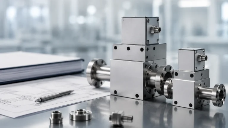
In industrial process control, the measurement of gauge sensor pressure is a fundamental requirement for monitoring fluid levels, ensuring vessel integrity, and optimizing automated workflows. Unlike absolute pressure, which is referenced against a perfect vacuum, gauge pressure is referenced against the local atmospheric pressure. This distinction is critical in level measurement applications, particularly when using hydrostatic transmitters in vented tanks or open reservoirs.
For engineers and plant operators, understanding the nuances of how a gauge sensor pressure transmitter operates is essential for selecting the right instrumentation. This guide explores the underlying physics, technical specifications, and practical application of gauge pressure sensors within the context of industrial level measurement.
Understanding Gauge Pressure in Industrial Level Measurement
Pressure measurement is categorized based on the reference point used for the zero value. To effectively deploy a gauge sensor pressure device, one must distinguish it from other pressure types:
* Gauge Pressure (psig, bar g): Measured relative to the ambient atmospheric pressure. The sensor diaphragm is exposed to the process on one side and atmospheric pressure on the other (usually via a vent tube or a hole in the sensor housing). When the process pressure equals the atmospheric pressure, the output is zero.
* Absolute Pressure (psia, bar a): Measured relative to a full vacuum. These sensors are used when atmospheric fluctuations would interfere with the accuracy of the process measurement, or in vacuum distillation processes.
* Differential Pressure (psid): Measures the difference between two distinct pressure points. This is commonly used in pressurized (closed) tanks to cancel out the head pressure of the gas blanket.
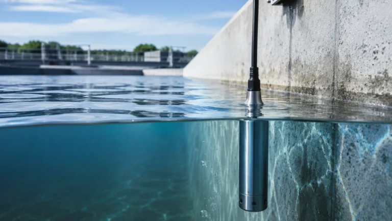
In most level measurement scenarios, such as water storage or open chemical vats, gauge pressure is the standard. Because the surface of the liquid is also under atmospheric pressure, using a gauge sensor naturally cancels out the effect of changing weather patterns or altitude, leaving only the pressure exerted by the liquid column itself.
Principles of Hydrostatic Level Measurement
Hydrostatic level measurement relies on the principle that the pressure at the bottom of a liquid column is directly proportional to the height of the liquid and its density. The formula used is:
P = ρ × g × h
Where:
* P is the hydrostatic pressure (measured by the gauge sensor pressure transmitter).
* ρ (rho) is the density of the liquid (kg/m³).
* g is the acceleration due to gravity (approximately 9.81 m/s²).
* h is the height of the liquid column (meters).
Because gravity is constant and the density of many industrial fluids is known, the pressure reading can be converted into a precise level measurement. If the density of the fluid changes (for example, due to temperature fluctuations), the sensor reading will reflect a change in pressure even if the physical level remains the same. Therefore, density compensation is a vital consideration for high-accuracy applications.
Technical Specifications and Construction
Modern gauge sensor pressure transmitters are engineered to withstand harsh industrial environments. Welk provides a range of solutions that utilize different sensing technologies depending on the chemical and physical properties of the media.
Sensing Elements
1. Piezoresistive Silicon Sensors: These sensors utilize a silicon chip with strain gauges diffused into it. They offer high sensitivity and excellent long-term stability. They are typically protected by a thin stainless steel diaphragm and filled with silicone oil to transfer pressure from the process to the chip.
2. Ceramic Capacitive Sensors: Known for their extreme robustness, ceramic sensors are highly resistant to abrasion and chemical corrosion. They are often used in wastewater or slurry applications where suspended solids might damage a metallic diaphragm.
Materials of Construction
The choice of wetted materials is dictated by the compatibility with the process fluid. Common options include:
* 316L Stainless Steel: The standard for water, oil, and non-corrosive chemicals.
* Hastelloy C: Required for highly aggressive media like acids or seawater.
* PTFE/PVDF: Coatings or solid housings used for maximum chemical resistance in the semiconductor or pharmaceutical industries.
Output Signals
To integrate into industrial automation systems, these sensors typically provide:
* 4-20 mA Analog: The industry standard for long-distance transmission with high noise immunity.
* HART Protocol: Allows for digital communication over the analog signal, enabling remote calibration and diagnostics.
* Modbus RTU/RS485: Common in digital networks and IoT-based monitoring systems.
Selection Criteria for Gauge Pressure Sensors
Selecting the appropriate gauge sensor pressure transmitter requires a detailed analysis of the application environment. The following table provides a general guideline for initial selection:
| Application | Media Type | Recommended Sensor Material | Typical Pressure Range |
| :— | :— | :— | :— |
| Municipal Water Tank | Clean Water | 316L Stainless Steel | 0–2 bar (approx. 20m) |
| Wastewater Treatment | Sludge/Effluent | Ceramic Diaphragm | 0–1 bar (approx. 10m) |
| Chemical Storage | Sulfuric Acid | Hastelloy C / PTFE | 0–5 bar (approx. 50m) |
| Fuel Oil Storage | Diesel / Oil | 316L Stainless Steel | 0–1.5 bar (approx. 15m) |
| Deep Well Monitoring | Groundwater | Titanium / 316L | 0–20 bar (approx. 200m) |
Environmental Factors
* Temperature: Ensure the sensor’s operating temperature range matches the process. High-temperature applications may require cooling fins or capillary tubes.
* Atmospheric Venting: Since a gauge sensor must "breathe" to reference the atmosphere, the vent tube in the cable must be protected from moisture. If water enters the vent tube, it can damage the internal electronics or cause measurement drift.
Installation Considerations and Best Practices
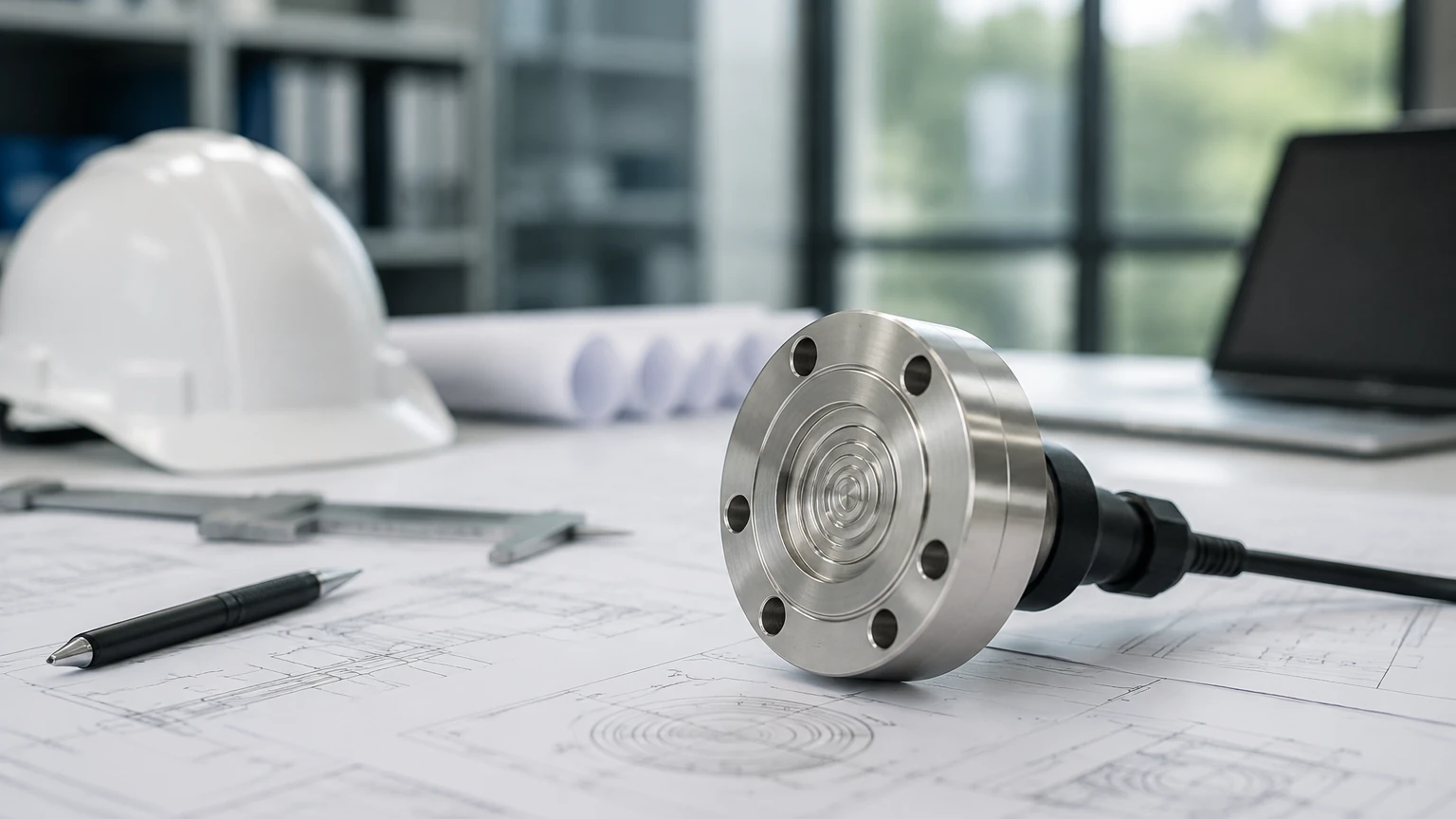
Proper installation is as important as sensor selection. For gauge sensor pressure transmitters, specific steps must be taken to ensure longevity and accuracy.
1. Mounting Location: The sensor should be mounted at the lowest point of the measurement range. In tanks with heavy sediment, the sensor should be raised slightly above the bottom or installed in a stilling well to prevent clogging.
2. Cable Management: For submersible sensors, the cable contains a small vent tube. This cable should be secured to prevent mechanical stress. Avoid sharp bends that could kink the vent tube, as this would prevent the sensor from accurately referencing atmospheric pressure.
3. Moisture Protection: Use a desiccant box or a specialized vent filter at the termination point of the cable. This prevents humid air from being drawn into the sensor housing, which could lead to internal condensation.
4. Zero Calibration: After installation, it is often necessary to perform a zero-point adjustment to account for the exact mounting height and any initial offsets. For comprehensive technical support and to Review product options and application support, engineers should consult the manufacturer's documentation.
Limitations and Troubleshooting
While gauge sensor pressure transmitters are reliable, they have specific limitations:
* Density Sensitivity: As mentioned, the sensor measures weight, not volume. If the fluid density changes by 1%, the level reading will also change by 1%.
* Dynamic Pressure Errors: If the sensor is placed near an inlet where fluid is moving at high velocity, the Bernoulli effect can cause a pressure drop, leading to an inaccurate low-level reading.
* Clogging: In viscous or fibrous fluids, the diaphragm may become coated or blocked. Regular inspection and the use of flush-diaphragm designs can mitigate this risk.
Common Troubleshooting Steps:
* Drifting Readings: Check the vent tube for blockages or moisture. Ensure the desiccant is still active.
* No Signal: Verify the power supply (typically 12-36V DC) and check for cable breaks or loose terminals.
* Erratic Output: This is often caused by electrical interference. Ensure the sensor cable is shielded and that the shield is grounded at the controller end only.
Frequently Asked Questions (FAQ)
Q: Can I use a gauge pressure sensor in a pressurized tank?
A: No. In a pressurized tank, the sensor would measure the liquid level plus the gas pressure. For pressurized vessels, a differential pressure transmitter is required to subtract the gas pressure from the total pressure.
Q: How often should a gauge sensor pressure transmitter be calibrated?
A: For most industrial applications, an annual calibration check is sufficient. However, in critical or high-accuracy applications, semi-annual checks may be required.
Q: What is the difference between a vented and a sealed gauge sensor?
A: A vented gauge sensor has a physical path to the atmosphere. A sealed gauge sensor is referenced to a fixed pressure (usually 1 atmosphere) sealed within the sensor. Sealed gauge sensors are used in high-pressure applications where atmospheric changes are negligible compared to the process pressure.
Conclusion
Gauge sensor pressure transmitters remain the workhorse of industrial level measurement due to their simplicity, reliability, and cost-effectiveness. By understanding the relationship between pressure, density, and height, and by following strict installation protocols regarding atmospheric venting, operators can achieve precise and stable level monitoring. Whether dealing with municipal water supplies or complex chemical processing, selecting a high-quality sensor tailored to the specific media and environmental conditions is the key to operational success. For more detailed specifications and to explore the full range of industrial measurement solutions, visit the Main Page of our technical catalog.