Cone Meter
Cone Meter
In the landscape of industrial flow measurement, the cone meter—frequently referred to as a V-cone meter—stands as a sophisticated evolution of differential pressure (DP) technology. While traditional DP devices like orifice plates have dominated the market for decades, the unique geometry of the cone meter addresses many of the inherent limitations found in older designs. For process engineers and instrumentation specialists, understanding the mechanical principles, installation requirements, and selection criteria of the cone meter is essential for optimizing system efficiency in water treatment, chemical processing, and oil and gas applications.
Measurement Principles of the Cone Meter
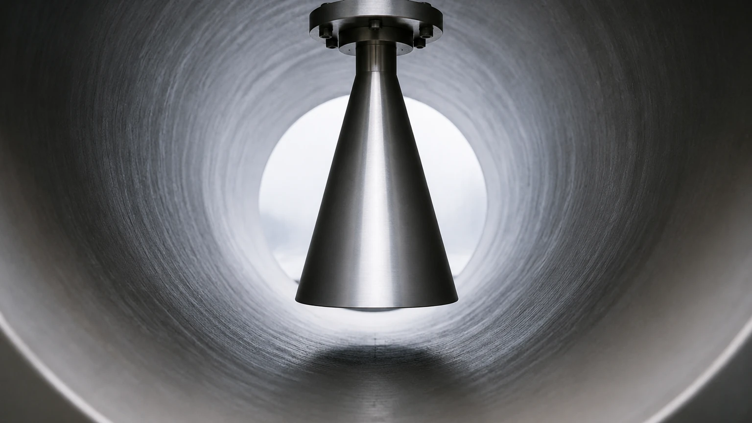
The cone meter operates based on the Bernoulli principle, which states that for an inviscid flow, an increase in the speed of the fluid occurs simultaneously with a decrease in pressure or a decrease in the fluid's potential energy. Unlike an orifice plate, which constricts flow through a central aperture, the cone meter utilizes a centrally located cone-shaped element suspended within the pipe.
The Velocity Profile Transformation
One of the most significant technical advantages of the cone meter is its ability to reshape the fluid’s velocity profile. In a standard pipe, fluid velocity is highest at the center and lowest near the pipe walls due to friction. When the fluid encounters the cone, it is forced to move toward the periphery of the pipe. This action flattens the velocity profile, effectively "conditioning" the flow before it reaches the measurement point.
As the fluid passes the largest diameter of the cone (the beta edge), a low-pressure zone is created immediately downstream. The differential pressure is measured between a high-pressure tap located upstream of the cone and a low-pressure tap located at the center of the cone's downstream face. Because the cone interacts with the entire flow profile rather than just the center, the resulting DP signal is remarkably stable and accurate, even under turbulent conditions.
Mathematical Foundation
The flow rate calculation for a cone meter follows the standard DP flow equation:
Q = C * A * √(2ΔP/ρ)
Where:
* Q is the flow rate.
* C is the discharge coefficient (specific to the cone geometry).
* A is the throat area (the annular space between the cone and the pipe wall).
* ΔP is the differential pressure.
* ρ (rho) is the fluid density.
Technical Advantages in Industrial Process Control
The adoption of cone meters in modern industrial facilities is driven by several performance-based factors that distinguish them from venturi tubes or orifice meters.
Reduced Straight Pipe Requirements
Traditional flow meters often require 10 to 40 diameters of straight pipe upstream to ensure a fully developed flow profile. The self-conditioning nature of the cone meter allows for significantly shorter runs. In many applications, a cone meter can operate accurately with only 0 to 3 diameters of straight pipe upstream and 0 to 1 diameter downstream. This compact footprint is invaluable in offshore platforms, skid-mounted systems, and retrofitted plants where space is at a premium.
High Turndown Ratio
Turndown ratio refers to the range of flow rates a meter can measure accurately. While standard orifice plates typically offer a 3:1 or 4:1 turndown, high-quality cone meters can achieve 10:1 or even 12:1. This allows a single instrument to handle significant fluctuations in process demand without the need for multiple meter runs or frequent recalibration.
Durability and Low Maintenance
The "scouring" effect of the fluid passing over the cone prevents the accumulation of debris and prevents the edge-wear common in orifice plates. Because the beta edge of the cone is not subject to the same impact forces as an orifice edge, the discharge coefficient remains stable over much longer periods, reducing the frequency of maintenance cycles.
For engineers seeking to integrate these flow solutions with advanced level monitoring, reviewing comprehensive product options and application support on the Main Page of specialized manufacturers like Welk can provide a broader perspective on total process automation. While Welk focuses on radar and ultrasonic level sensors, the integration of DP-based flow and level measurement remains a cornerstone of industrial efficiency.
Selection Criteria and Material Compatibility
Choosing the correct cone meter requires a detailed analysis of the process fluid, pressure ratings, and environmental conditions. The following table outlines the typical selection parameters for industrial-grade cone meters.
Practical Selection Table
| Parameter | Standard Specification | High-Performance Option |
| :— | :— | :— |
| Accuracy | ±0.5% of flow rate | ±0.1% (with calibration) |
| Repeatability | ±0.1% | ±0.05% |
| Turndown Ratio | 10:1 | Up to 30:1 with stacked transmitters |
| Pressure Loss | Low (typically <20% of DP) | Ultra-low loss designs available |
| Beta Ratio Range | 0.45 to 0.85 | Custom ratios for specific ΔP |
| Standard Materials | SS316L, Carbon Steel | Hastelloy, Monel, Duplex SS |
| Line Sizes | 15 mm to 1200 mm | Custom sizes up to 3000 mm |
| Pressure Rating | PN16 to PN100 | Up to PN400 (ANSI 2500#) |
Installation Considerations
While the cone meter is more forgiving than other technologies, proper installation is still vital for maintaining the stated accuracy of the instrument.
1. Orientation: The meter can be installed in horizontal, vertical, or inclined positions. However, for liquid service in horizontal lines, the DP taps should be positioned below the horizontal centerline to prevent gas entrapment. For gas service, the taps should be above the centerline to avoid liquid accumulation.
2. Transmitter Connection: Impulse lines should be as short as possible. In high-temperature applications, cooling elements or siphons may be necessary to protect the DP transmitter.
3. Flow Direction: The cone meter is a directional device. Reversing the flow will result in incorrect readings and potential damage to the cone support structure. Always verify the flow arrow engraved on the meter body.
4. Welding and Gaskets: Ensure that gaskets do not protrude into the flow stream, as this can create turbulence that the cone cannot fully compensate for, leading to measurement noise.
Limitations and Potential Risks
Despite its versatility, the cone meter is not a universal solution for every application. Engineers should be aware of the following limitations:
* Initial Capital Cost: The manufacturing of a cone meter involves precision machining and welding of the internal cone, making it more expensive than a simple orifice plate or a basic magnetic flow meter.
* Permanent Pressure Loss: Although lower than an orifice plate, the cone meter does induce a permanent pressure loss in the system. This must be accounted for in pump sizing and energy consumption calculations.
* Sizing Complexity: Unlike standard DP devices that can be sized using general ISO 5167 formulas, cone meters often require proprietary sizing software from the manufacturer to accurately predict the discharge coefficient for a specific geometry.
Comparison with Level Measurement Technologies
In many B2B industrial environments, flow measurement and level measurement are intrinsically linked. For example, in a chemical reactor, a cone meter may monitor the inflow of reactants while a radar level meter monitors the total volume.
Welk, as a professional manufacturer, provides a range of level measurement instruments—including radar level meters, ultrasonic sensors, and hydrostatic transmitters—that complement flow measurement systems. While the cone meter handles the dynamic movement of fluids, these level instruments ensure the static or semi-static inventory is managed with high precision. Hydrostatic level transmitters, in particular, share the same underlying DP technology as the cone meter, using the weight of the liquid column to determine level, much like the cone uses fluid velocity to determine flow.
Frequently Asked Questions (FAQs)
Q: Can a cone meter measure wet gas?
A: Yes. The cone meter is particularly effective in wet gas applications. Because the cone forces the flow to the pipe walls, it prevents the "damming" effect of liquids that often plagues orifice plates in gas lines. It can typically handle higher liquid fractions than most other DP devices.
Q: Is calibration necessary for every cone meter?
A: While many manufacturers provide a "calculated" discharge coefficient based on geometric similarity, a flow lab calibration is highly recommended for applications requiring better than ±1.0% accuracy. Calibration accounts for minor manufacturing variances in the cone's edge and positioning.
Q: How does the cone meter handle high-viscosity fluids?
A: The cone meter performs well at lower Reynolds numbers compared to orifice plates. However, as viscosity increases, the discharge coefficient may become less linear. It is important to consult the manufacturer's performance curves if the Reynolds number is expected to drop below 10,000.
Q: What is the typical lifespan of a cone meter?
A: In non-corrosive environments, the primary element (the cone and body) can last 20 to 25 years. The electronics (DP transmitter) typically have a service life of 10 to 15 years, depending on the environment and maintenance schedule.
Conclusion
The cone meter represents a robust, high-performance solution for challenging flow measurement tasks where space is limited and accuracy is paramount. By understanding the interaction between the cone geometry and the fluid velocity profile, engineers can implement systems that require less maintenance and provide more reliable data over the long term. When paired with reliable level measurement solutions, such as those found on the Main Page, the cone meter becomes a vital component in a comprehensive industrial automation strategy.