Head Box
Head Box
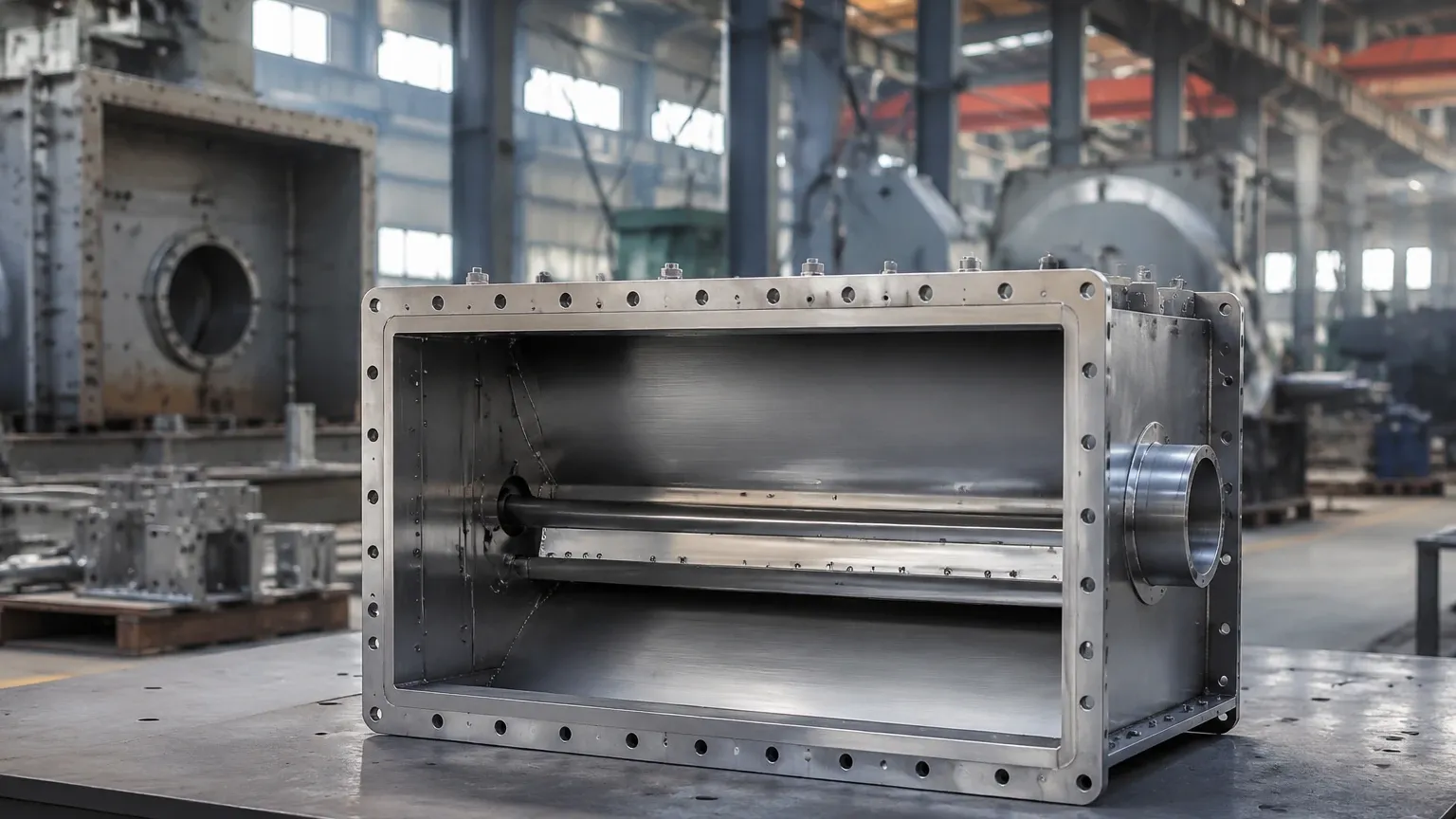
In the pulp and paper industry, the headbox stands as one of the most critical components of the paper machine. It is the final pressurized or gravity-fed chamber that distributes a dilute mixture of water and fibers—known as stock—onto the forming wire. The primary function of the headbox is to transform the pipe flow into a uniform, rectangular discharge across the entire width of the machine.
Maintaining a precise liquid level and internal pressure within the headbox is fundamental to ensuring paper quality. Fluctuations in level lead to variations in the "jet-to-wire" ratio, which directly impacts the basis weight, moisture content, and tensile strength of the final product. For engineers and plant operators, selecting the correct level measurement technology is essential for process stability and minimizing waste. This guide examines the technical requirements for headbox level monitoring and the instrumentation used to achieve high-accuracy control.
Measurement Principles for Head Box Applications
Level measurement in a headbox is complicated by the nature of the medium (fibrous stock) and the mechanical design of the vessel. There are three primary technologies employed: hydrostatic pressure, non-contact radar, and ultrasonic sensing.
Hydrostatic Pressure Measurement
Hydrostatic level measurement operates on the principle that the pressure at a specific point in a static liquid is proportional to the height of the liquid column above it. The formula used is $P = \rho \cdot g \cdot h$, where $P$ is pressure, $\rho$ (rho) is the density of the stock, $g$ is gravity, and $h$ is the height.
In an open (atmospheric) headbox, a single pressure transmitter mounted at the bottom provides a direct level reading. However, most modern high-speed machines use pressurized (air-cushioned) headboxes. In these systems, a differential pressure (DP) approach is required. One sensor measures the total pressure at the bottom (liquid + air cushion), while a second sensor measures the air pressure at the top. The system subtracts the air pressure from the total pressure to isolate the liquid level.
Non-Contact Radar (FMCW)
Frequency Modulated Continuous Wave (FMCW) radar is increasingly favored for headbox applications. The sensor emits a continuous microwave signal with a changing frequency. The signal reflects off the surface of the stock and returns to the sensor. The frequency difference between the emitted and received signal is proportional to the distance.
Radar is highly effective because it is independent of changes in density or temperature. High-frequency radar (such as 80 GHz) provides a narrow beam angle, which is advantageous in the confined spaces of a headbox where internal baffles or agitators might otherwise cause false reflections.
Ultrasonic Measurement
Ultrasonic sensors function by emitting high-frequency sound pulses. The time taken for the pulse to travel to the surface and back determines the distance. While cost-effective, ultrasonic technology is sensitive to the air temperature and vapor density within the headbox. In pressurized systems where the air cushion may contain varying levels of humidity or temperature gradients, ultrasonic sensors require compensation to maintain accuracy.
Key Evaluation Criteria for Head Box Level Sensors
When selecting instrumentation for a headbox, several technical factors must be evaluated to ensure long-term reliability and performance.
1. Chemical and Physical Compatibility: The stock consists of water, wood fibers, and various chemical additives (fillers, sizing agents, and dyes). All wetted parts of the sensor, particularly diaphragms for hydrostatic transmitters, must be made of corrosion-resistant materials like 316L stainless steel or Hastelloy.
2. Stock Buildup and Clogging: Paper stock has a tendency to dewater and form a mat on surfaces. For hydrostatic sensors, a flush-mount diaphragm is mandatory to prevent the stock from entering a sensing port and clogging. For non-contact sensors, the antenna should be designed to resist condensation and splash-back.
3. Accuracy and Response Time: Because the headbox operates at high speeds, the level control loop must be extremely responsive. Sensors should offer high resolution (typically within ±1 mm to ±3 mm) and a fast refresh rate to allow the PLC or DCS to make real-time adjustments to the pump speed or air cushion pressure.
4. Pressure Ratings: In hydraulic or air-cushioned headboxes, the sensor must be rated for the maximum operating pressure of the vessel, which can reach several bars in high-speed machines.
Selection Table for Head Box Level Measurement
The following table compares the most common technologies used in headbox level control to assist in the selection process.
| Feature | Hydrostatic (Flush Diaphragm) | Non-Contact Radar (80 GHz) | Ultrasonic Sensors |
| :— | :— | :— | :— |
| Measurement Accuracy | High (if density is constant) | Excellent (±1 mm) | Moderate |
| Influence of Foam | None | Minimal (depending on density) | High (absorbs sound) |
| Installation Type | Wetted (Contact) | Non-Contact | Non-Contact |
| Maintenance Needs | Moderate (diaphragm cleaning) | Very Low | Low |
| Effect of Pressure | Requires DP for pressurized | No Effect | Sensitive to air density |
| Best Application | Open or low-speed boxes | High-speed, pressurized boxes | Open, stable environments |
Installation Considerations and Best Practices
Proper installation is as critical as the choice of technology. Incorrect placement can lead to turbulent readings or premature sensor failure.
Mounting Location
The sensor should be mounted in a location that represents the average level of the stock. It must be kept away from the "slice" (the exit nozzle) and the inlet pipes where turbulence is highest. If the headbox contains internal showers for foam control, the sensor should be positioned to avoid direct spray.
Avoiding Obstructions
For radar and ultrasonic sensors, the "beam path" must be clear of internal structural supports, pipes, or agitators. Even with modern software that can "mask" fixed reflections, a clear line of sight to the stock surface ensures the strongest signal-to-noise ratio.
Stilling Wells
In cases of extreme surface turbulence or heavy foam, a stilling well (a vertical pipe submerged in the liquid) can be used to provide a calm surface for the sensor to measure. However, in headbox applications, stilling wells must be designed to be easily cleaned, as fiber buildup inside the well can cause the internal level to lag behind the actual level in the box.
Calibration and Zeroing
For hydrostatic sensors, the "zero" point must be accurately set relative to the bottom of the headbox. For differential pressure systems, the capillary tubes or impulse lines (if used) must be purged of air to prevent measurement errors. Modern digital transmitters often feature a "one-touch" zeroing function that simplifies this process during machine shutdowns.
Common Challenges and Limitations
Despite advancements in technology, certain environmental factors remain challenging for headbox level control.
* Entrained Air and Foam: Paper stock often contains entrained air, and foam can accumulate on the surface. Foam can dissipate ultrasonic pulses and, if dense enough, can cause a false high reading for radar. In these scenarios, hydrostatic sensors are often superior because they measure the mass of the liquid and are unaffected by surface foam.
* Density Fluctuations: If the consistency of the stock (the ratio of fiber to water) changes significantly, the density changes. Since hydrostatic pressure depends on density, this will introduce an error in the level reading. If the mill runs many different grades of paper with varying consistencies, non-contact radar is the more reliable choice.
* Vibration: Paper machines generate significant mechanical vibration. Level transmitters must be ruggedized and mounted with vibration-dampening brackets if necessary to prevent electronic failure or signal noise.
Frequently Asked Questions (FAQs)
Q: Why is level control in the headbox so important for paper quality?
A: The level (and pressure) determines the velocity at which the stock exits the slice. If the velocity is not synchronized with the speed of the forming wire, the fibers will not orient correctly, leading to poor sheet formation and uneven thickness.
Q: Can I use a float-type level switch in a headbox?
A: It is not recommended. The wood fibers in the stock will quickly coat the float and the pivot mechanism, causing it to stick. Non-contact or flush-mount sensors are the industry standard.
Q: How does the air cushion affect the level reading?
A: In a pressurized headbox, the air cushion adds pressure to the liquid. A standard pressure sensor would interpret this as a higher liquid level. To correct this, you must use a differential pressure system or a non-contact radar that is unaffected by the air pressure.
Q: What maintenance is required for a headbox level sensor?
A: For hydrostatic sensors, the diaphragm should be inspected during scheduled shutdowns for any signs of pitting or buildup. For radar sensors, the antenna lens should be wiped clean if there is significant splashing or condensation buildup.
Conclusion
Selecting the right level measurement solution for a headbox requires a thorough understanding of the machine's operating parameters, including pressure, stock consistency, and the presence of foam. While hydrostatic transmitters remain a reliable and cost-effective choice for many applications, the precision and low-maintenance nature of 80 GHz radar make it the preferred option for high-speed, modern paper production. To explore a wide range of industrial level measurement instruments tailored for water treatment, chemical, and automation applications, you can visit the Main Page of Welk's product catalog for detailed specifications and engineering support.
By following established installation guidelines and considering the specific physical properties of the paper stock, mill operators can ensure stable headbox levels, leading to consistent paper quality and reduced operational downtime.