High Leak Detected Connect Your Tubing
High Leak Detected Connect Your Tubing
In industrial process automation, the error message "High Leak Detected Connect Your Tubing" serves as a critical diagnostic alert for systems relying on pneumatic or hydrostatic pressure to determine liquid levels. Whether encountered in a bubbler-style level measurement system, a differential pressure (DP) transmitter setup, or an automated chemical dispensing unit, this notification indicates that the instrument’s internal sensors have detected a pressure drop or flow rate inconsistency that exceeds calibrated tolerances.
For engineers and maintenance technicians, addressing this alert is not merely about physical reconnection; it requires a systematic understanding of fluid dynamics, seal integrity, and the specific measurement principles governing the hardware. This guide explores the technical foundations of level measurement systems that utilize tubing, the causes of leak-related errors, and the engineering standards for maintaining a sealed process environment.
Understanding the "High Leak Detected" Alert in Level Measurement
When an industrial controller displays "High Leak Detected Connect Your Tubing," it is typically responding to a feedback loop from a pressure transducer or a mass flow controller. In level measurement applications, tubing is used to convey a pressure signal from the process point to the sensing element. If the integrity of this conduit is compromised, the resulting data becomes unreliable, potentially leading to tank overflows, pump cavitation, or dry-run conditions.
The alert usually triggers under two primary conditions:
1. Pressure Decay: In static systems (like hydrostatic impulse lines), the sensor detects a steady drop in pressure while the process level remains constant.
2. Flow Excess: In dynamic systems (like air bubblers), the system must increase the gas flow rate beyond a safety threshold to maintain the required back-pressure, suggesting that gas is escaping through a breach in the tubing or a loose fitting.
Measurement Principles: The Role of Tubing in Fluid Level Monitoring
To effectively troubleshoot leak-related errors, one must first understand the measurement principles where tubing is a primary component. Welk provides various instruments that interface with these systems, ensuring accurate data transmission from the process to the control room.
1. Hydrostatic Bubbler Systems
The bubbler (or air-purge) method is one of the most robust technologies for measuring levels in open or vented tanks, especially those containing corrosive or slurry-laden liquids. A tube is submerged to a fixed depth in the vessel. A regulated gas (usually air or nitrogen) is pushed through the tubing. The pressure required to displace the liquid and form bubbles at the bottom of the tube is directly proportional to the hydrostatic head (level) of the liquid.
* The Tubing Role: The tubing acts as the primary conduit for the purge gas.
* Leak Impact: If a leak occurs in the tubing above the liquid line, the pressure sensor will record a lower value than the actual head pressure, causing the system to under-report the liquid level.
2. Differential Pressure (DP) with Impulse Lines
DP transmitters measure the difference in pressure between two points. In many installations, the transmitter is located away from the tank, connected via "impulse lines" (small-diameter tubing). These lines may be filled with the process fluid or a sealing liquid.
* The Tubing Role: The tubing transmits the exact process pressure to the high-pressure and low-pressure sides of the transmitter diaphragm.
* Leak Impact: A leak in an impulse line creates a pressure gradient that does not exist in the tank, leading to significant measurement drift.
3. Pneumatic Level Switches
Some mechanical level switches use a pneumatic pilot signal. When the float reaches a certain point, it opens or closes a valve, changing the air pressure in a control line to trigger an alarm or pump.
Technical Causes of Tubing Leaks and Signal Loss
When a system prompts the user to "connect your tubing," the root cause often extends beyond a simple disconnection. Common technical failures include:
* Vibration Fatigue: In environments with heavy machinery or high-velocity flow, constant vibration can cause compression fittings to back off or cause metal tubing to work-harden and crack.
* Chemical Incompatibility: Using standard polyurethane or PVC tubing in the presence of aggressive solvents or high-temperature vapors can lead to softening, swelling, or brittle fracture.
* Improper Bend Radii: If tubing is forced into a tight 90-degree turn without proper elbow fittings, the wall of the tube may kink or develop micro-fractures over time.
* Thermal Expansion: Significant temperature swings in outdoor tank farms can cause tubing and fittings to expand and contract at different rates, eventually compromising the seal at the ferrule.
Selection Criteria for Industrial Level Instrument Tubing
Selecting the correct materials is the first step in preventing the "High Leak Detected" error. Engineers must match the tubing specifications to the chemical and physical demands of the application. Reviewing professional product options at the Main Page can help in identifying the right instrumentation for specific environmental challenges.
| Tubing Material | Temperature Range | Chemical Resistance | Common Application |
| :— | :— | :— | :— |
| 316 Stainless Steel | -250°C to +600°C | Excellent | High-pressure DP impulse lines, steam applications. |
| PTFE (Teflon) | -200°C to +260°C | Superior | Corrosive chemical tanks, bubbler tubes in acids. |
| PFA | -200°C to +260°C | Superior | High-purity water, semiconductor processing. |
| Polyurethane (PU) | -40°C to +60°C | Moderate | Standard air-purge lines in non-corrosive water treatment. |
| Copper | -196°C to +200°C | Good | General purpose pneumatic control (non-ammonia environments). |
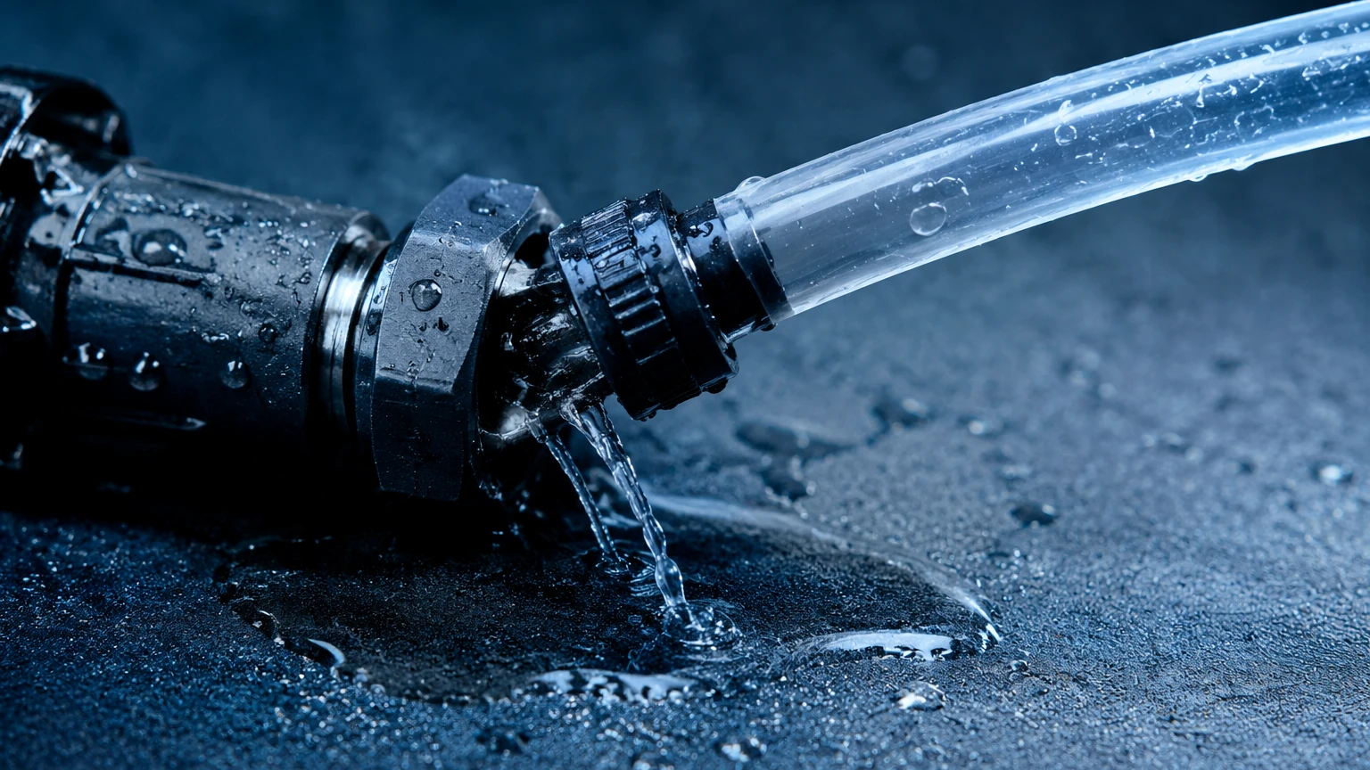
Step-by-Step Troubleshooting: Connect Your Tubing and Restore Integrity
When the "High Leak Detected" alert persists, follow this systematic engineering checklist to identify and resolve the breach:
1. Visual Inspection: Check the entire length of the tubing for kinks, discolorations (indicating chemical attack), or physical abrasions. Ensure the tubing is properly seated in all push-to-connect or compression fittings.
2. Fitting Integrity: Use a calibrated torque wrench to ensure compression fittings (such as Swagelok or similar) are tightened to the manufacturer’s specification. Over-tightening can deform the ferrule and cause leaks just as easily as under-tightening.
3. Pressure Decay Test: Isolate the tubing section from the process. Pressurize the line to 1.5 times the maximum operating pressure (not exceeding the tubing's burst rating) and monitor the pressure gauge over 10–30 minutes. A drop in pressure confirms a leak.
4. Ultrasonic Leak Detection: For high-pressure gas lines or air-purge systems, use an ultrasonic leak detector. These devices pick up the high-frequency turbulence created by escaping gas, even in noisy industrial environments.
5. Bubble Test: In lower-pressure applications, applying a certified leak-detection solution (soap-based) to joints will reveal leaks through the formation of bubbles.
Installation Best Practices for Leak-Free Level Measurement
To ensure long-term reliability and avoid the "High Leak Detected Connect Your Tubing" error, adhere to these installation guidelines:
* Support and Bracing: Tubing should be supported every 0.5m to 1.0m (approx. 20 to 40 inches) using cushioned clamps to minimize the effects of vibration.
* Sloping Impulse Lines: For hydrostatic or DP measurements, impulse tubing should be sloped at least 1:12 (8%). For gas applications, slope the tubing toward the process to allow condensate to drain back into the tank. For liquid applications, slope toward the sensor to prevent air pockets.
* Deburring: When cutting metal tubing, always use a deburring tool to remove internal and external burrs. Foreign particles can migrate to the sensor diaphragm or prevent a ferrule from seating correctly.
* Avoid Mixing Materials: Avoid using brass fittings with stainless steel tubing, as galvanic corrosion can occur, particularly in humid or coastal environments.
Limitations of Pneumatic and Hydrostatic Tubing Systems
While tubing-based systems like bubblers are highly effective, they have inherent limitations. The maximum distance between the sensor and the process point is limited by the internal volume of the tubing; excessively long lines (over 300 meters or approx. 1000 feet) can introduce a significant time lag in measurement response. Furthermore, in cryogenic applications, any moisture in the air-purge line can freeze, completely blocking the tubing and triggering a high-leak or high-pressure error.
In scenarios where tubing maintenance is prohibitive, engineers may consider transitioning to non-contact technologies. Welk offers advanced radar and ultrasonic level meters that eliminate the need for impulse lines or submerged tubes, thereby removing the risk of pneumatic leaks entirely.
Frequently Asked Questions (FAQ)
Q: Why does the error persist after I have reconnected the tubing?
A: The error may be latched in the controller's software. After securing the connections, you may need to perform a "Reset" or "Clear Fault" command on the HMI. Additionally, check if the internal O-ring within the fitting has been nicked or worn out.
Q: Can I use plastic tubing for all level measurement applications?
A: No. Plastic tubing (like PE or PU) is generally limited to pressures below 10 bar (145 psi) and temperatures below 60°C. For high-pressure steam or high-temperature oil, stainless steel impulse piping is required.
Q: How often should tubing connections be inspected?
A: In high-vibration or thermal-cycling environments, a quarterly inspection is recommended. For stable, indoor environments, an annual check during routine calibration is usually sufficient.
Q: Does the diameter of the tubing affect the leak detection sensitivity?
A: Yes. Smaller diameter tubing (e.g., 6mm or 1/4 inch) will show a more rapid pressure drop for a given leak size compared to larger diameter tubing, making the system more sensitive to minor breaches.
For technical specifications on the transmitters and sensors that power these systems, or to explore alternatives to tubing-dependent measurements, visit the Main Page for comprehensive product data and application support.