High Speed Pressure Transducer
High Speed Pressure Transducer
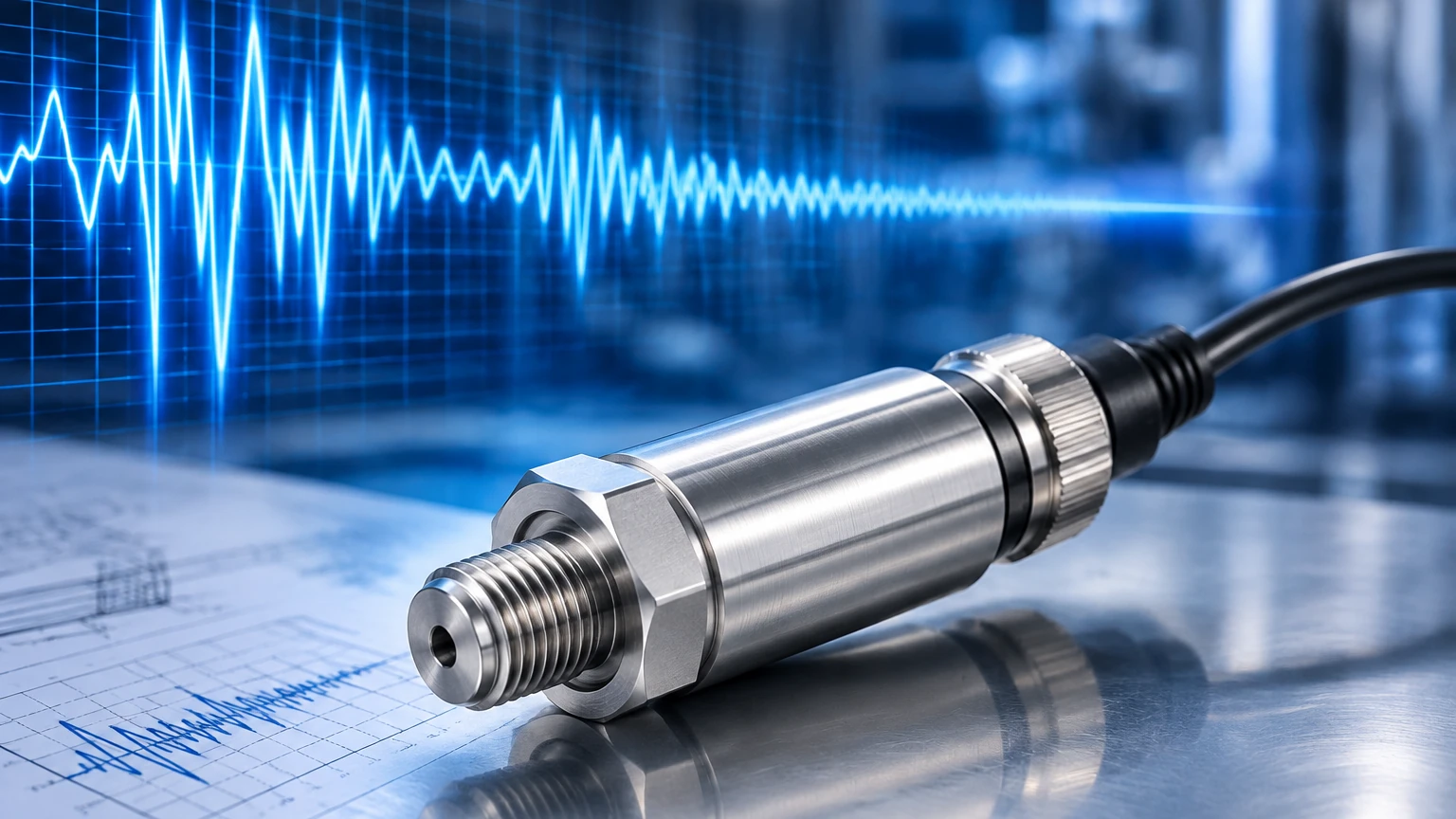
In industrial automation and process engineering, the ability to monitor pressure changes in real-time is critical for system safety and performance. While standard pressure transmitters are suitable for steady-state monitoring, certain applications involve rapid fluctuations, shock waves, or high-frequency pulsations. This is where a high speed pressure transducer becomes an essential tool. Unlike conventional sensors that may have response times in the tens or hundreds of milliseconds, high-speed variants are designed to capture data at microsecond intervals, providing a detailed view of dynamic fluid and gas behavior.
Understanding the nuances of these instruments is vital for engineers tasked with system design, particularly in sectors like aerospace, automotive testing, and high-pressure hydraulics. This guide explores the measurement principles, selection criteria, and installation requirements for high-speed pressure sensing technology.
Measurement Principles of High-Speed Transducers
Before selecting a high speed pressure transducer, it is necessary to understand the underlying physical principles that enable rapid response. The choice of sensing element dictates how the sensor reacts to transient pressure events.
Piezoelectric Sensors
Piezoelectric transducers utilize crystals (such as quartz) or ceramic materials that generate an electrical charge when subjected to mechanical stress. These are inherently dynamic sensors. They are exceptionally fast, often capable of measuring events with rise times of less than one microsecond (1 µs).
* Advantages: Extremely high frequency response, high stiffness, and compact size.
* Limitations: They cannot measure static (constant) pressure. The charge eventually leaks away, making them unsuitable for long-term level monitoring or steady-state pressure measurement.
Piezoresistive (Silicon-on-Insulator) Sensors
Piezoresistive transducers use a silicon diaphragm with integrated strain gauges. When pressure is applied, the resistance of the gauges changes. While many piezoresistive sensors are designed for static use, high-end versions utilize micro-machined (MEMS) technology to achieve high natural frequencies.
* Advantages: Capable of measuring both static and dynamic pressure (DC to several hundred kHz).
* Limitations: Generally more sensitive to temperature fluctuations than piezoelectric types, requiring sophisticated compensation.
Thin-Film Strain Gauge Sensors
These sensors involve sputtering a thin layer of resistive material onto a stainless-steel diaphragm. They are known for their long-term stability and robustness in harsh environments.
* Advantages: Excellent durability and resistance to shock.
* Limitations: Typically have lower frequency responses compared to piezoelectric or MEMS-based piezoresistive sensors, usually topping out at 10–20 kHz.
Key Performance Metrics for High-Speed Sensing
When evaluating a high speed pressure transducer, the following technical specifications are the most critical for ensuring the device can keep up with the process.
1. Natural Frequency
The natural frequency (or resonant frequency) of the sensor diaphragm determines the upper limit of its speed. As a rule of engineering, the maximum frequency of the pressure event being measured should not exceed 20% to 30% of the sensor's natural frequency to avoid signal distortion caused by resonance.
2. Rise Time
Rise time refers to the time it takes for the transducer output to change from 10% to 90% of a step-pressure input. For high-speed applications like explosion testing or fuel injection analysis, rise times in the microsecond range are mandatory.
3. Sampling Rate and Bandwidth
In the context of the entire measurement chain, the bandwidth of the transducer must be matched by the data acquisition (DAQ) system. If a transducer has a bandwidth of 100 kHz but the DAQ only samples at 10 kHz, the high-speed data is lost to aliasing.
Practical Selection Table
To assist in the initial screening of technologies, the following table compares common sensor types based on their dynamic capabilities.
| Feature | Piezoelectric | Piezoresistive (High Speed) | Thin-Film |
| :— | :— | :— | :— |
| Primary Measurement | Dynamic only | Static & Dynamic | Static & Semi-Dynamic |
| Frequency Response | Up to 1 MHz | Up to 500 kHz | Up to 20 kHz |
| Rise Time | < 1 µs | 1–5 µs | > 50 µs |
| Temperature Stability | Excellent | Moderate (Requires Comp) | High |
| Typical Application | Shock waves, Ballistics | Hydraulics, Turbines | Industrial Process Control |
Application Scenarios
High-speed pressure measurement is rarely used for simple tank level monitoring unless the process involves rapid filling or explosive decompression. Common industrial use cases include:
* Hydraulic System Analysis: Detecting "water hammer" or pressure spikes that can damage valves and seals in high-pressure circuits (often exceeding 400 bar).
* Internal Combustion Engine Testing: Monitoring cylinder pressure cycles where changes occur within milliseconds.
* Turbomachinery: Measuring blade pass frequency and flow instabilities in compressors and turbines.
* Aerospace Testing: Wind tunnel measurements and rocket motor combustion stability.
For standard industrial level and pressure applications where high-speed transients are not the primary concern, engineers often refer to a Main Page of instrumentation to find a balance between accuracy and cost-effectiveness.
Installation Considerations and Best Practices
The physical installation of a high speed pressure transducer is as important as the sensor's specifications. Improper mounting can introduce errors that render high-speed data useless.
Flush Mounting vs. Recessed Mounting
* Flush Mounting: The sensor diaphragm is mounted exactly level with the inner wall of the pipe or vessel. This is the preferred method for high-speed measurement as it eliminates "dead volume" and prevents the formation of standing waves or Helmholtz resonance.
* Recessed Mounting: The sensor is set back behind a small port or tube. While this protects the diaphragm from heat or debris, it creates a cavity that acts as a low-pass filter, severely limiting the high-frequency response and potentially causing false pressure oscillations.
Signal Conditioning and Cabling
High-speed signals are highly susceptible to electromagnetic interference (EMI).
1. Cabling: Use shielded twisted-pair cables. For piezoelectric sensors, low-noise coaxial cables are mandatory to prevent "triboelectric" noise (noise generated by cable movement).
2. Impedance Matching: Ensure the input impedance of the recording device matches the output requirements of the transducer to prevent signal reflection and loss.
3. Grounding: Implement a single-point ground to avoid ground loops, which can obscure high-frequency data with 50/60 Hz hum or high-frequency switching noise from VFDs (Variable Frequency Drives).
Thermal Protection
In high-speed combustion or aerospace applications, the sensor may be exposed to extreme heat. Recessed mounting with a cooling jacket or using a specialized heat shield (ablative coating) may be necessary, though these solutions must be balanced against the loss of frequency response.
Limitations and Common Risks
While high-speed transducers offer incredible insights, they come with specific trade-offs:
* Fragility: High-speed diaphragms are often very thin to minimize mass and increase natural frequency. This makes them susceptible to damage from overpressure or mechanical impact (e.g., particles in the flow).
* Data Overload: Sampling at 1 MHz generates massive amounts of data. Engineers must ensure they have the storage and processing power to handle the output.
* Cost: Due to the specialized materials and calibration required, a high speed pressure transducer can be significantly more expensive than a standard industrial transmitter.
* Signal Drift: Especially in piezoresistive models, rapid temperature changes during a high-speed event can cause thermal drift, which may be mistaken for a pressure change if not properly compensated.
Frequently Asked Questions (FAQ)
Q: Can I use a high-speed transducer for regular tank level measurement?
A: While possible with piezoresistive types, it is generally not cost-effective. Piezoelectric types cannot be used for this at all, as they do not measure static pressure. For standard level applications, refer to specialized hydrostatic or radar level meters.
Q: What is the difference between a pressure transmitter and a pressure transducer?
A: In technical terms, a transducer converts pressure into a low-level electrical signal (like mV), while a transmitter includes signal conditioning to provide a higher-level output (like 4-20mA or 0-10V). High-speed applications usually use transducers because the conditioning circuitry in transmitters can slow down the response time.
Q: How do I know if my application requires a high-speed sensor?
A: If you are seeing unexplained component failures (cracked pipes, blown seals) or if your current pressure readings appear as a flat line during a known dynamic event, you likely need a sensor with a higher frequency response.
Q: How often should these sensors be calibrated?
A: Because they are often used in extreme conditions, annual calibration is a minimum. For critical R&D testing, many facilities calibrate before and after a major test series.
Conclusion
Selecting the right high speed pressure transducer requires a deep understanding of both the physical process and the limitations of sensing technology. By prioritizing natural frequency and ensuring a flush-mount installation, engineers can capture the transient data necessary to optimize high-performance systems. For those managing broader industrial processes, integrating these specialized sensors with standard measurement arrays ensures both the safety of the infrastructure and the accuracy of the data. To explore a wider range of industrial measurement solutions, engineers are encouraged to consult a Main Page for technical documentation and product specifications across various sensing categories.