How Do You Calibrate a Flow Meter
How Do You Calibrate a Flow Meter
In industrial process control, the accuracy of fluid measurement is paramount for safety, efficiency, and fiscal accountability. Whether managing water treatment facilities, chemical processing plants, or oil and gas pipelines, engineers must ensure that their instrumentation provides reliable data. A critical component of this reliability is the periodic verification of measurement accuracy. But how do you calibrate a flow meter effectively? This guide examines the fundamental principles, methodologies, and practical considerations involved in the calibration of flow measurement devices.
Principles of Flow Measurement and Calibration
Before addressing the specific steps of calibration, it is essential to understand the underlying measurement principles. Flow meters generally measure either the volume or the mass of a fluid passing through a specific point over time. Common technologies include electromagnetic, ultrasonic, differential pressure (DP), and Coriolis meters.
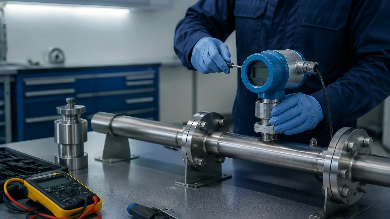
Calibration is the process of comparing the readings of a flow meter (the unit under test, or UUT) against a reference standard of known, higher accuracy. This reference standard must be traceable to national or international standards, such as those maintained by NIST (National Institute of Standards and Technology) or equivalent bodies. The goal is to quantify the error in the UUT and, if necessary, adjust the device to bring it within the manufacturer’s specified tolerance.
In many industrial setups, flow measurement is intrinsically linked to level measurement. For instance, in open-channel flow applications, an ultrasonic level sensor measures the height of liquid passing over a weir or through a flume. The flow rate is then calculated based on the level-to-flow relationship defined by the geometry of the structure. Calibrating these systems requires verifying both the level sensor's accuracy and the mathematical conversion used by the transmitter. For comprehensive solutions in both level and flow monitoring, engineers often refer to the Main Page of specialized instrument manufacturers to ensure their hardware meets the required process specifications.
Primary Methods of Flow Meter Calibration
There are several established methods for calibrating flow meters, each suited to different fluid types, flow rates, and accuracy requirements. The choice of method often depends on whether the calibration is performed in a laboratory setting or on-site (in-situ).
1. The Master Meter Method
This is perhaps the most common industrial calibration technique. It involves placing a high-precision "master meter" in series with the meter being tested. A fluid is pumped through both meters at a constant rate.
* Procedure: The readings from the UUT are compared directly to the readings from the master meter.
* Advantages: It is relatively fast and can be performed in the field if a portable master meter is available.
* Limitations: The master meter itself must be calibrated frequently, and its uncertainty must be significantly lower (typically 3 to 4 times better) than the UUT.
2. Gravimetric (Weight) Method
Widely considered the most accurate method, the gravimetric approach measures the mass of fluid that passes through the meter over a specific time interval.
* Procedure: Fluid is directed through the flow meter into a collection tank mounted on a high-precision weighing scale. The weight of the fluid is measured, and the time taken to collect it is recorded. If the meter measures volume, the fluid's density must be precisely known to convert mass to volume.
* Advantages: High degree of accuracy; it is a fundamental measurement of mass.
* Limitations: Primarily used in laboratory environments due to the size and sensitivity of the weighing equipment.
3. Volumetric Method
Similar to the gravimetric method, this technique measures the volume of fluid collected rather than its mass.
* Procedure: Fluid is passed through the meter into a calibrated volumetric vessel (often called a "prover"). These vessels have precisely known internal volumes.
* Advantages: It eliminates the need for density corrections if the meter under test is a volumetric device.
* Limitations: Temperature fluctuations can cause the fluid to expand or contract, introducing errors if not strictly controlled.
Step-by-Step Calibration Procedure
While the specific steps vary depending on the meter type and the chosen method, a standard industrial calibration generally follows this sequence:
1. System Preparation: Ensure the system is free of leaks and that the fluid is stable. Air bubbles in liquid lines or moisture in gas lines can significantly skew results. The meter should be installed according to the manufacturer’s guidelines regarding straight pipe runs.
2. Zeroing the Meter: Before starting flow, the meter should be checked for a "zero" reading under no-flow conditions. Many modern digital meters allow for a zero-point adjustment to account for installation stresses.
3. Multi-Point Testing: Calibration should never be performed at a single flow rate. Typically, a minimum of three to five points across the meter’s operating range (e.g., 25%, 50%, 75%, and 100% of maximum flow) are tested to identify non-linearity.
4. Data Collection and Calculation: Record the UUT readings and the reference standard readings for each point. Calculate the error percentage using the formula:
\[ \text{Error \%} = \left( \frac{\text{Meter Reading} – ext{Reference Reading}}{\text{Reference Reading}} \right) \times 100 \]
5. Adjustment and Verification: If the error exceeds the allowable tolerance, the meter’s K-factor or scaling parameters are adjusted. After adjustment, a second "as-left" calibration run is performed to verify the fix.
Selection Table for Calibration Methods
The following table provides a general guideline for selecting a calibration method based on application needs.
| Method | Best For | Typical Accuracy | Environment |
| :— | :— | :— | :— |
| Master Meter | General industrial use, field verification | 0.5% – 1.0% | Field or Lab |
| Gravimetric | High-precision chemical/fuel measurement | 0.02% – 0.1% | Laboratory |
| Volumetric | Water utilities, large volume transfers | 0.1% – 0.5% | Lab or Prover Station |
| Piston Prover | Low flow rates, high-viscosity fluids | 0.05% – 0.1% | Laboratory |
Installation and Environmental Considerations
How do you calibrate a flow meter if the installation environment is working against you? Environmental factors are often the primary cause of calibration failure or measurement drift.
Piping Geometry
Most flow meters require a certain length of straight pipe upstream and downstream to ensure a fully developed, non-turbulent flow profile. Obstructions like elbows, valves, or pumps create swirls and velocity profile distortions. If the calibration setup does not mimic the field installation, the results may not be representative of actual performance.
Fluid Properties
Changes in temperature and pressure affect fluid density and viscosity. For gas flow measurement, these changes are dramatic. Calibration must either be performed at the operating temperature and pressure or corrected using the ideal gas law or real gas equations. For liquids, viscosity changes can affect the Reynolds number, which in turn affects the meter's discharge coefficient.
Ambient Conditions
In outdoor installations, extreme ambient temperatures can affect the electronics of the transmitter. High-quality instruments, such as those found via the Main Page, often include internal temperature compensation to mitigate these effects, but this must still be verified during the calibration process.
Limitations and Common Risks
Calibration is not a panacea for all measurement issues. There are inherent limitations and risks that engineers must manage:
* Turndown Ratio Limits: A meter calibrated at high flow rates may become highly inaccurate at the lower end of its range. Always ensure the calibration covers the actual expected operating range.
* Hysteresis: This occurs when the meter provides different readings for the same flow rate depending on whether the flow is increasing or decreasing. Identifying hysteresis requires testing points in both ascending and descending order.
* Traceability Gaps: If the reference standard's own calibration has expired, the entire calibration process for the UUT is technically invalid for regulatory compliance.
* Human Error: Manual data entry and timing errors in gravimetric or volumetric methods remain common sources of uncertainty.
Frequently Asked Questions (FAQs)
Q: How often should a flow meter be calibrated?
A: The frequency depends on the criticality of the measurement, the fluid's abrasiveness/corrosiveness, and regulatory requirements. Most industrial standards suggest an annual calibration, though stable processes may extend this to every two years.
Q: Can I calibrate a flow meter using water if it will be used for oil?
A: Only if the meter's performance is independent of viscosity (like some electromagnetic meters) or if accurate Reynolds number corrections are applied. For many meters, it is best to calibrate with a fluid that has similar properties to the process fluid.
Q: What is the difference between calibration and validation?
A: Calibration involves comparing a device against a standard and making adjustments. Validation (or verification) is a simpler check to ensure the device is still performing within a specified range without necessarily making adjustments.
Q: How does air entrainment affect calibration?
A: Air bubbles in a liquid flow significantly increase the measured volume in volumetric meters and cause signal scattering in ultrasonic meters, leading to large positive errors or complete signal loss.
Conclusion
Understanding how do you calibrate a flow meter is essential for maintaining the integrity of industrial processes. By selecting the appropriate method—whether it be the master meter, gravimetric, or volumetric approach—and adhering to strict procedures regarding piping geometry and fluid properties, engineers can ensure their data is both accurate and defensible.
Reliable measurement starts with selecting the right hardware designed for the specific rigors of the application. For those integrating level and flow systems, consulting a professional manufacturer ensures that the instruments provided are capable of maintaining their calibration over long service lives. For more information on selecting industrial-grade measurement technology, visit the Main Page to explore the latest in radar, ultrasonic, and hydrostatic measurement solutions.