关系使用说明书gl
关系使用说明书gl
In the realm of industrial automation and process control, the accuracy of level measurement is predicated on the precise "relationship" (关系) between the physical state of the medium and the electronic interpretation of the sensor. This document, serving as a technical reference or instruction manual (使用说明书), focuses on the "gl" (guided/general level) parameters essential for optimizing Welk level measurement instruments. Establishing a reliable measurement relationship ensures operational safety, inventory accuracy, and process efficiency across industries such as water treatment, chemical processing, and oil and gas.
1. Fundamental Measurement Principles
Before configuring the relationship between a sensor and its environment, it is vital to understand the underlying physics of the selected technology. Welk provides several core technologies, each governed by specific physical laws.
1.1 Radar Level Measurement (Time of Flight)
Radar level meters utilize high-frequency electromagnetic waves (typically 26GHz or 80GHz). The instrument emits a signal that travels to the surface of the medium, reflects, and returns to the sensor. The relationship between distance ($D$) and time ($t$) is defined by the formula:
$$D = \frac{c \cdot t}{2}$$
Where $c$ is the speed of light. In a "gl" configuration, the transmitter must be calibrated to recognize the "Empty" and "Full" points relative to the tank height. High-frequency 80GHz radar allows for a narrower beam angle, reducing the risk of interference from internal tank structures like agitators or ladders.
1.2 Ultrasonic Level Sensors
Similar to radar, ultrasonic sensors use the Time of Flight (ToF) principle but employ sound waves instead of electromagnetic waves. The speed of sound is significantly slower and is influenced by air temperature and gas composition. Therefore, the "relationship" in ultrasonic manuals often includes temperature compensation algorithms to maintain accuracy as the ambient environment shifts.
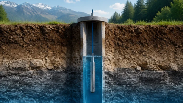
1.3 Hydrostatic Level Transmitters
Hydrostatic measurement relies on the relationship between pressure and liquid height. The pressure ($P$) at the bottom of a liquid column is proportional to the height ($h$) of the liquid, the density ($\rho$) of the medium, and gravity ($g$):
$$P = \rho \cdot g \cdot h$$
For this relationship to remain accurate, the density of the liquid must remain constant, or the system must be recalibrated if the medium changes.
2. Establishing the "gl" Relationship: Configuration and Calibration
The term "关系使用说明书gl" refers to the systematic mapping of the physical tank dimensions to the instrument’s output signal (usually 4-20mA or a digital protocol like HART or RS485).
2.1 Zero-Point and Span Calibration
To establish a functional relationship, the user must define:
- Zero Point (0%): The distance from the sensor reference plane to the bottom of the tank (or the lowest desired measurement level).
- Full Point (100%): The distance from the sensor reference plane to the maximum liquid level.
In Welk instruments, the "gl" instructions emphasize that the 100% mark should never enter the "Dead Zone" (Blocking Distance) of the sensor, which is the area immediately below the antenna where measurement is impossible due to the physics of signal ringing.
2.2 Dielectric Constant ($ε_r$) and Signal Strength
In radar measurement, the relationship between the reflected signal strength and the medium is determined by the dielectric constant. Liquids with high $ε_r$ (like water, $ε_r ≈ 80$) reflect signals strongly, while hydrocarbons (like oil, $ε_r ≈ 2$) reflect weakly. The instruction manual for these applications requires adjusting the sensitivity threshold to ensure the "relationship" between the pulse and the surface is correctly identified against background noise.
3. Practical Selection Table
Choosing the correct instrument is the first step in ensuring a successful measurement relationship. The following table provides a guideline for technology selection based on application needs.
| Technology | Recommended Media | Max Range | Key Advantages | Limitations |
| :— | :— | :— | :— | :— |
| 80GHz Radar | Corrosive liquids, solids, high-temp | 120m | Narrow beam, high precision (±1mm) | Higher initial cost |
| Ultrasonic | Water, wastewater, open channels | 15m | Non-contact, cost-effective | Affected by foam and vacuum |
| Hydrostatic | Water, oils, fuel tanks | 200m | Simple installation, very stable | Density must be known/constant |
| Magnetic Gauge | High-pressure boilers, chemicals | 6m | Visual indication + remote output | Mechanical parts in contact |
| Level Switch | Overfill protection (all media) | N/A | High reliability for point level | No continuous measurement |
For a comprehensive review of these technologies and to find specific model numbers, users should refer to the Main Page of the official Welk documentation.
4. Installation Considerations and Best Practices
The physical installation of the sensor directly impacts the mathematical relationship between the signal and the level. Improper placement can lead to "false echoes" or signal attenuation.
4.1 Nozzle Geometry
The height and diameter of the mounting nozzle are critical. If a nozzle is too narrow or too long, the radar or ultrasonic beam may reflect off the nozzle walls before reaching the medium. The general rule is that the sensor antenna should extend at least 10mm past the bottom of the nozzle into the tank space.
4.2 Avoiding Obstructions
Internal structures such as heating coils, support beams, or inlet pipes can create interference. When setting up the "gl" relationship, many modern Welk transmitters allow for "False Echo Suppression." This process records the signals from static obstructions and subtracts them from the measurement relationship, allowing the sensor to focus only on the moving liquid surface.
4.3 Orientation and Turbulence
- Radar/Ultrasonic: Must be mounted perpendicular to the liquid surface. In turbulent tanks, a stilling well or bypass pipe may be required to maintain a stable relationship between the sensor and the surface.
- Hydrostatic: Should be mounted away from areas of high turbulence (like near an agitator) to prevent pressure fluctuations that would be misinterpreted as level changes.

5. Limitations and Environmental Factors
No measurement relationship is universal. Engineers must account for environmental variables that can degrade accuracy.
1. Foam: Heavy, thick foam can absorb ultrasonic and radar signals. For applications with significant foaming, hydrostatic transmitters or guided wave radar (GWR) are often preferred over non-contact methods.
2. Vapor and Condensation: While radar is largely unaffected by vapor, ultrasonic waves travel at different speeds through different gas densities. Condensation on the sensor face can also cause a "blind" condition, requiring specialized antenna designs (like PTFE drop antennas).
3. Pressure and Temperature: Extreme temperatures can shift the calibration of electronic components. Welk instruments are designed with robust housing, but the "gl" manual specifies operating limits (e.g., -40°C to +200°C for standard radar) that must be respected to maintain the integrity of the data relationship.
6. Maintenance and Troubleshooting FAQ
How do I verify the relationship between the output signal and the actual level?
Perform a "dip tape" measurement manually and compare it to the instrument's reading. If the instrument reads 5.00m and the manual measurement is 5.05m, an offset adjustment is required in the configuration menu.
What causes a "Signal Loss" error in the gl manual?
Signal loss usually occurs if the dielectric constant of the medium is too low, the surface is too turbulent, or there is excessive foam. Increasing the "Gain" or "Sensitivity" in the instrument settings can sometimes restore the relationship.
Can I use a water-calibrated hydrostatic sensor for oil?
No. Because oil has a lower density than water, a sensor calibrated for water will provide a lower level reading than the actual height of the oil. You must adjust the density parameter ($\rho$) in the transmitter's software to correct the relationship.
What is the significance of the "gl" designation in Welk manuals?
The "gl" designation typically refers to the "General Level" or "Guided Level" logic used in the firmware to process complex signal returns into a linear 4-20mA output. It ensures that even in non-linear tanks (like horizontal cylindrical tanks), the relationship between volume and level is calculated correctly through strapping tables.
7. Conclusion
Understanding the "关系使用说明书gl" (Relationship Instruction Manual gl) is essential for any engineer or technician tasked with liquid level monitoring. By correctly defining the physical and electronic relationship between the sensor and the process medium, facilities can achieve higher precision and reduce the risk of overflows or dry-run conditions.
Welk continues to lead the industry by providing versatile measurement solutions that simplify these complex relationships. For further technical specifications, wiring diagrams, or to consult with an application engineer regarding your specific measurement needs, please visit the Main Page. Accurate level measurement is not just about the hardware; it is about mastering the relationship between the instrument and the environment it serves.