How Does an Ultrasonic Flow Meter Work
How Does an Ultrasonic Flow Meter Work
In the realm of industrial process control, the ability to accurately measure fluid flow without interrupting the process or compromising the integrity of the piping system is a significant advantage. Ultrasonic flow meters have emerged as a premier solution for these requirements. As a specialized technology utilized extensively in water treatment, chemical processing, and oil and gas industries, understanding the underlying physics and operational mechanics is essential for engineers and plant managers. This guide explores the fundamental principles, selection criteria, and practical application of ultrasonic flow measurement technology.
Fundamental Measurement Principles
To understand how does an ultrasonic flow meter work, one must distinguish between the two primary methods of measurement: Transit-Time and Doppler Effect. While both utilize ultrasonic sound waves—typically at frequencies ranging from 0.5 to 5 MHz—their interaction with the fluid differs significantly.
Transit-Time Ultrasonic Flow Meters
The transit-time principle is the most common method for measuring clean liquids. This technique relies on the fact that sound waves traveling in the direction of fluid flow move faster than those traveling against it.
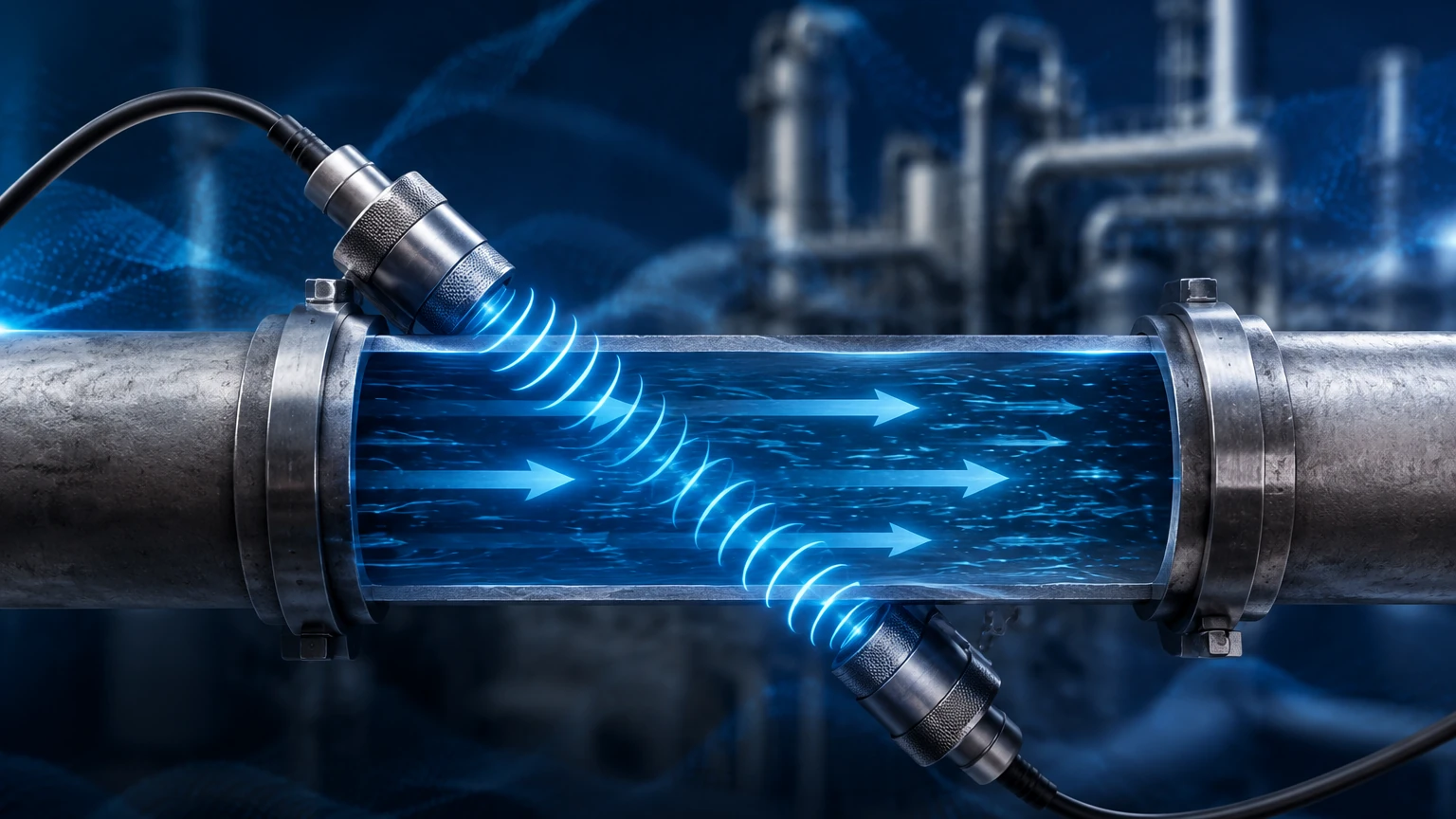
A transit-time meter employs a pair of transducers (A and B) mounted on the pipe. Transducer A sends an ultrasonic pulse to Transducer B (downstream), and then Transducer B sends a pulse back to Transducer A (upstream).
* Downstream Time ($t_{ab}$): The time taken for the signal to travel with the flow.
* Upstream Time ($t_{ba}$): The time taken for the signal to travel against the flow.
The difference in these travel times ($Δt$) is directly proportional to the velocity of the fluid. The electronic transmitter processes this time difference, along with the pipe geometry and fluid properties, to calculate the volumetric flow rate. Because the time differences are often in the nanosecond range, high-precision electronics are required to maintain accuracy.
Doppler Effect Ultrasonic Flow Meters
Unlike transit-time meters, Doppler flow meters require the presence of "reflectors" within the fluid, such as suspended solids, sediment, or entrained gas bubbles. This method is based on the principle discovered by Christian Doppler in 1842.
A transducer emits an ultrasonic signal of a known frequency into the moving fluid. This signal reflects off the particles or bubbles. Because the reflectors are moving, the frequency of the reflected signal is shifted (the Doppler shift).
* If the fluid is moving toward the transducer, the reflected frequency is higher.
* If the fluid is moving away, the reflected frequency is lower.
The shift in frequency is proportional to the velocity of the reflectors. While Doppler meters are less accurate than transit-time meters for clean fluids, they are indispensable for slurries, wastewater, and aerated liquids where transit-time signals would be blocked or scattered.
Components and System Architecture
A standard ultrasonic flow measurement system consists of three primary components: the transducers, the signal processor (transmitter), and the interconnecting cabling.
1. Transducers (Sensors): These contain piezoelectric crystals that convert electrical energy into mechanical vibrations (ultrasound) and vice versa. They can be "clamp-on" (mounted to the outside of the pipe) or "wetted/inline" (inserted into the flow stream).
2. Transmitter/Converter: This is the "brain" of the system. It generates the electrical pulses, receives the return signals, performs the mathematical calculations (including temperature compensation), and provides outputs such as 4-20mA, pulse, or digital protocols (Modbus, HART).
3. Pipe Interface: For clamp-on models, a coupling agent (grease or epoxy) is used to eliminate air gaps between the transducer and the pipe wall, ensuring efficient signal transmission.
Practical Selection Criteria
Choosing the right ultrasonic meter requires an analysis of the fluid characteristics and the physical environment. The following table provides a comparison to assist in the selection process.
| Feature | Transit-Time Meter | Doppler Meter |
| :— | :— | :— |
| Fluid Type | Clean liquids, low turbidity | Slurries, aerated liquids, wastewater |
| Particulate Content | < 2% by volume | > 100 ppm (minimum size ~100 μ) |
| Accuracy | High (0.5% to 2% of velocity) | Moderate (2% to 5% of velocity) |
| Pipe Sizes | 10 mm to 5000 mm | 25 mm to 5000 mm |
| Installation | Inline or Clamp-on | Primarily Clamp-on |
| Best Use Case | Potable water, chemicals, oils | Raw sewage, mining slurries, dredging |
When evaluating high-performance instrumentation for complex industrial environments, it is often beneficial to Review product options and application support to ensure the selected hardware meets specific pressure and temperature ratings.
Installation Guidelines and Best Practices
The accuracy of an ultrasonic flow meter is heavily dependent on the installation environment. Because these meters measure velocity, they are sensitive to flow profile distortions caused by elbows, valves, and pumps.
Straight Pipe Run Requirements
To ensure a fully developed, symmetrical flow profile, the "10D and 5D" rule is the standard engineering benchmark.
* Upstream: A minimum of 10 pipe diameters (10D) of straight, unobstructed pipe before the sensors.
* Downstream: A minimum of 5 pipe diameters (5D) of straight pipe after the sensors.
If the upstream piping includes a pump or a double elbow in different planes, the upstream requirement may increase to 20D or 40D to allow turbulence to subside.
Transducer Mounting Methods (Clamp-on)
For clamp-on applications, there are three primary mounting configurations:
* V-Method: The signals bounce off the opposite pipe wall once. This is the standard for pipes ranging from 25 mm to 400 mm.
* Z-Method: Transducers are mounted on opposite sides of the pipe. The signal crosses the pipe once. This is used for large pipes or highly attenuative materials where signal strength is a concern.
* W-Method: The signal bounces three times. This is reserved for very small pipes (under 50 mm) where the transit time needs to be artificially lengthened to improve resolution.
Pipe Condition and Coupling
The pipe must be full at all times. If air pockets exist at the top of the pipe, the ultrasonic signal will be lost. Furthermore, the external surface of the pipe must be cleaned of rust, loose paint, or scale. A high-quality acoustic couplant must be applied to the transducer face to facilitate the transfer of sound energy into the pipe wall.
Limitations and Environmental Factors
While highly versatile, ultrasonic technology is not a universal solution. Engineers must account for the following limitations:
* Pipe Material: Materials with high acoustic attenuation, such as certain plastics (HDPE) or lined pipes (cement or rubber-lined), can weaken the signal. If the liner is not perfectly bonded to the pipe wall, the air gap will prevent the signal from passing through.
* Temperature Extremes: High temperatures can damage piezoelectric crystals. Standard transducers typically handle up to 80°C, while specialized high-temperature versions can reach 250°C.
* Reynolds Number: At very low flow velocities (laminar flow), the flow profile is parabolic. The meter must be programmed with the correct Reynolds number compensation to adjust the velocity measurement for the transition from turbulent to laminar flow.
* Signal Interference: Variable Frequency Drives (VFDs) and heavy machinery can sometimes introduce electrical noise that interferes with the sensitive ultrasonic signals. Shielded cabling and proper grounding are mandatory.
Comparison with Other Flow Technologies
Compared to electromagnetic flow meters (magmeters), ultrasonic meters do not require the fluid to be conductive. This makes them ideal for deionized water and hydrocarbons. Unlike turbine or vortex meters, ultrasonic meters have no moving parts and create no pressure drop, reducing long-term maintenance costs and energy consumption in pumping systems.
Frequently Asked Questions (FAQs)
Q: Can an ultrasonic flow meter measure steam?
A: Most standard ultrasonic flow meters are designed for liquids. While specialized high-temperature gas ultrasonic meters exist for steam, they are significantly more complex and expensive than liquid versions.
Q: Does the pipe material affect accuracy?
A: Yes. The transmitter must know the exact sound speed of the pipe material (e.g., Carbon Steel vs. PVC) to calculate the refraction angle of the ultrasonic beam. Incorrect material settings will lead to significant measurement errors.
Q: Can I use a clamp-on meter on a pipe with a liner?
A: Yes, provided the liner is sonically conductive and well-bonded to the host pipe. If there is any air gap between the pipe and the liner, the signal will be reflected back, and measurement will be impossible.
Q: How often does the couplant need to be reapplied?
A: For permanent installations, solid epoxy couplants or high-viscosity silicone grease are used, which can last for years. For portable surveys, standard grease should be checked if the signal strength degrades over time.
Conclusion
Understanding how does an ultrasonic flow meter work involves a grasp of acoustic physics and fluid dynamics. By leveraging the transit-time or Doppler principles, these instruments provide a non-intrusive, reliable, and cost-effective way to monitor industrial processes. Whether the application involves clean water distribution or abrasive chemical slurries, selecting the correct technology and adhering to strict installation guidelines ensures long-term accuracy. For professionals seeking to integrate these solutions into their automation architecture, Welk offers a range of sophisticated measurement instruments designed for the rigors of modern industry.