How to Calibrate Pressure Transmitter
How to Calibrate Pressure Transmitter
In industrial process control, the accuracy of pressure transmitters is fundamental to operational safety, product quality, and system efficiency. Whether used for direct pressure monitoring or as a component of hydrostatic level measurement, these instruments must be regularly verified and adjusted. This guide provides a comprehensive technical overview of the principles of pressure measurement and a detailed walkthrough of how to calibrate pressure transmitter units in both bench and field environments.
Understanding Pressure Measurement Principles
Before detailing the calibration process, it is essential to understand the underlying technology of the instruments. Most modern pressure transmitters, such as those manufactured by Welk, utilize one of several sensing principles to convert physical force into an electrical signal, typically 4-20mA.
Piezoresistive Sensors
These sensors consist of a diaphragm with integrated strain gauges. When pressure is applied, the diaphragm deforms, changing the electrical resistance of the gauges. This change is measured using a Wheatstone bridge circuit. Piezoresistive sensors are highly sensitive and widely used in general-purpose industrial applications.
Capacitive Sensors
In a capacitive pressure transmitter, a sensing diaphragm is positioned between two fixed capacitor plates. As pressure moves the diaphragm, the capacitance between the diaphragm and the plates changes. This technology is known for its robustness and high accuracy, particularly in low-pressure or vacuum applications.
Hydrostatic Level Measurement
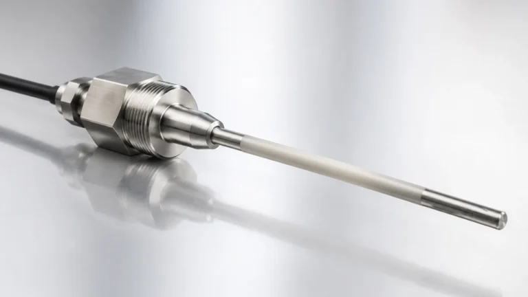
In the context of level measurement, pressure transmitters function based on the hydrostatic principle: the pressure at the bottom of a liquid column is proportional to the height of the liquid and its density ($P = \rho \cdot g \cdot h$). Calibrating a transmitter for level applications requires precise knowledge of the liquid's specific gravity to ensure the pressure reading accurately reflects the tank level.
Essential Tools for Pressure Transmitter Calibration
To perform a professional calibration, a technician requires a set of traceable and high-precision tools. The quality of the calibration is directly limited by the accuracy of the reference equipment.
1. Pressure Source: A hand pump (pneumatic for low pressure, hydraulic for high pressure) or a deadweight tester.
2. Reference Standard: A digital pressure gauge or a pressure calibrator with an accuracy at least four times better than the transmitter being tested (the 4:1 rule).
3. Multimeter or Loop Calibrator: To measure the 4-20mA output signal with high precision (at least 0.01mA resolution).
4. Power Supply: Typically a 24V DC source to power the current loop.
5. HART Communicator: For smart transmitters, a handheld terminal or PC interface is required to adjust digital parameters and perform sensor trims.
6. Manifold and Fittings: To securely connect the pressure source to the transmitter without leaks.
Step-by-Step Guide: How to Calibrate Pressure Transmitter
The calibration process involves comparing the transmitter's output against a known reference and adjusting it to minimize the error. This is usually performed as a 5-point check (0%, 25%, 50%, 75%, and 100% of the range).
1. Preparation and Setup
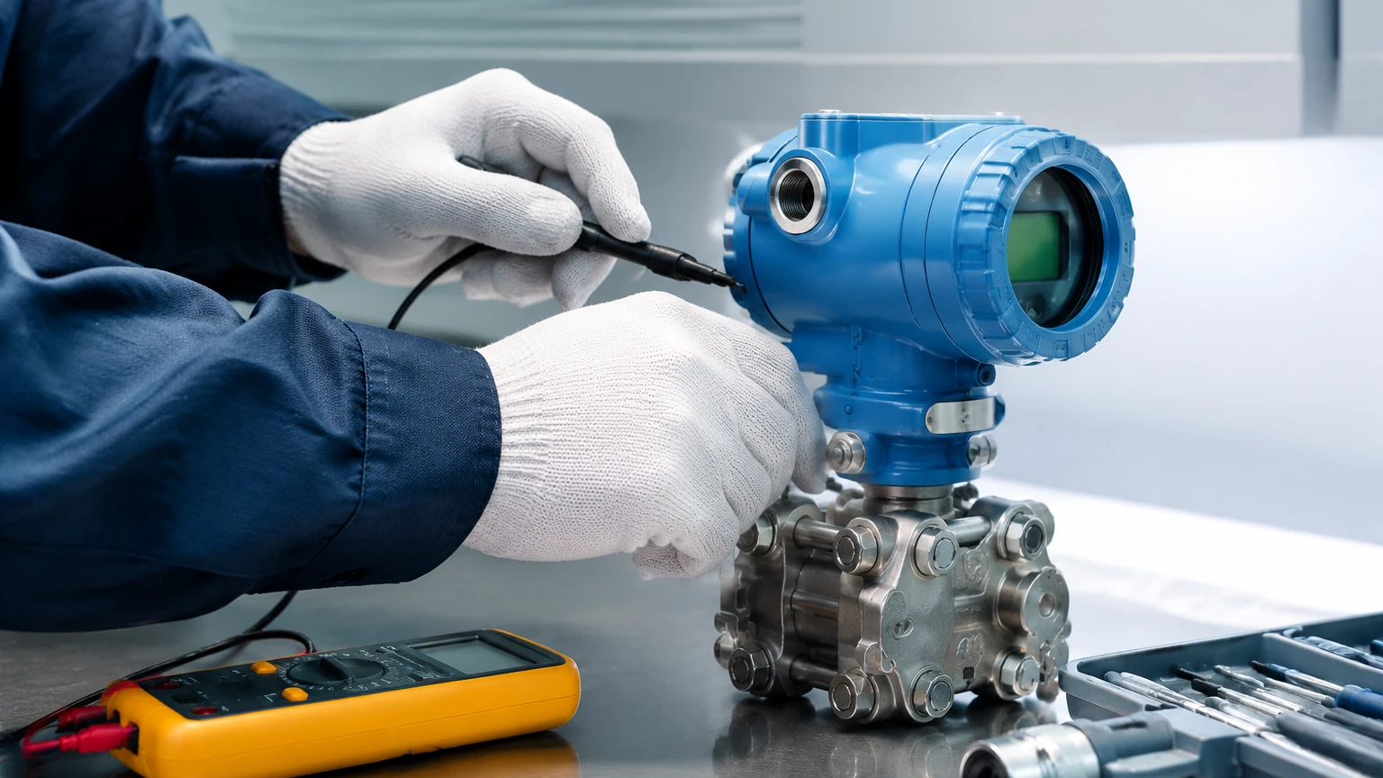
Before beginning, ensure the transmitter is isolated from the process. If performing a bench calibration, secure the transmitter in a vice. Connect the pressure source to the high-pressure port (and vent the low-pressure port if it is a differential transmitter). Connect the 24V DC power supply and the multimeter in series to measure the current loop.
2. The Zero Adjustment (0% Point)
Ensure the pressure source is at atmospheric pressure (0 bar gauge). The output should be exactly 4.00mA. If the reading deviates, use the "Zero" adjustment screw (on analog models) or the HART communicator to perform a "Zero Trim." This establishes the baseline for the entire range.
3. The Span Adjustment (100% Point)
Apply the maximum pressure of the transmitter's calibrated range using the pressure pump. For example, if the range is 0 to 10 bar, apply exactly 10.00 bar as shown on the reference gauge. The output should be 20.00mA. Adjust the "Span" setting until the output is correct. Note that adjusting the span may slightly affect the zero point, so a re-check is necessary.
4. Linearity Verification (5-Point Check)
After setting the zero and span, verify the intermediate points to ensure linearity:
* 25% Pressure: Output should be 8.00mA.
* 50% Pressure: Output should be 12.00mA.
* 75% Pressure: Output should be 16.00mA.
Record the actual mA readings at each point. If the error at any point exceeds the manufacturer's specified tolerance (e.g., ±0.05% of span), the instrument may require a sensor trim or may be reaching the end of its service life.
5. Hysteresis Check
Repeat the 5-point check in descending order (100% down to 0%). This identifies hysteresis—the difference in readings depending on whether the pressure was increasing or decreasing. Significant hysteresis often indicates mechanical fatigue in the diaphragm.
Calibration for Hydrostatic Level Applications
When a pressure transmitter is used as a hydrostatic level sensor, the calibration must account for the mounting position. If the transmitter is mounted below the bottom of the tank (a "wet leg" or simply a lower elevation), the constant pressure of the liquid in the impulse piping must be zeroed out. This is known as Zero Suppression.
Conversely, if the transmitter is mounted above the zero level of the tank, or if there is a pressurized vapor space that must be compensated for, Zero Elevation techniques are applied. During calibration, these offsets must be mathematically calculated and programmed into the transmitter to ensure the 4mA point corresponds to an empty tank and 20mA corresponds to a full tank.
Selection and Maintenance Table
Choosing the right instrument and maintaining its calibration schedule depends on the application environment. For more detailed specifications on various measurement technologies, you can visit the Main Page of our technical resource.
| Feature | Piezoresistive Transmitter | Capacitive Transmitter | Hydrostatic Level Probe |
| :— | :— | :— | :— |
| Best Use Case | General gas/liquid pressure | Vacuum & high-precision | Deep wells & open tanks |
| Calibration Frequency | Annual | Every 1-2 years | Bi-annual (due to fouling) |
| Typical Accuracy | 0.1% to 0.5% FS | 0.05% to 0.1% FS | 0.25% to 0.5% FS |
| Temperature Sensitivity | Moderate | Low | Low (submerged) |
| Maintenance Priority | Diaphragm cleaning | Electronics verification | Cable integrity & desiccant |
Installation Considerations and Limitations
Calibration accuracy is only useful if the installation is correct. Several factors can introduce errors that calibration cannot fix:
* Mounting Position: Most transmitters are calibrated in a vertical position. Mounting them horizontally can cause a zero shift due to the weight of the internal oil fill acting on the diaphragm. Always perform a zero trim in the final mounting orientation.
* Temperature Effects: While most Welk transmitters include temperature compensation, extreme ambient fluctuations can cause drift. Ensure the transmitter is shielded from direct solar radiation or extreme process heat.
* Impulse Line Clogging: In many industrial setups, the pressure is transmitted through small-bore pipes. If these clog, the transmitter will show a "frozen" or sluggish reading regardless of how well it is calibrated.
* Overpressure Events: Subjecting a transmitter to pressure beyond its Proof Pressure rating can permanently deform the diaphragm, leading to non-linear errors that cannot be calibrated out.
Frequently Asked Questions (FAQ)
How often should I calibrate my pressure transmitter?
Most industrial standards recommend an annual calibration. However, in critical safety loops or harsh environments (high vibration, corrosive media), a six-month interval may be required. If the instrument shows consistent stability over several cycles, the interval can be extended.
What is the difference between "Zeroing" and "Calibration"?
Zeroing is a simple adjustment to ensure the output is 4mA when there is no process pressure. Calibration is a full verification of the instrument's accuracy across its entire range using a traceable reference standard.
Can I calibrate a transmitter without a HART communicator?
If the transmitter is an older analog model, you can use the physical Zero and Span potentiometers. For modern smart transmitters, you can perform a basic zero/span adjustment if the unit has external buttons, but a full digital configuration and sensor trim require a HART communicator or similar digital interface.
Why is my transmitter showing 3.8mA or 20.5mA?
These are typically "NAMUR NE43" fault signals. A reading below 4mA or above 20mA usually indicates a sensor failure, a broken wire, or an over-range condition, rather than a simple calibration error.
Conclusion
Mastering how to calibrate pressure transmitter units is a vital skill for maintaining industrial process integrity. By following a structured 5-point verification and understanding the specific requirements of hydrostatic level applications, engineers can ensure long-term reliability. For further technical documentation, product selection guides, and advanced measurement solutions, please refer to our Main Page for comprehensive support.