Hvac Pressure Transmitter
Hvac Pressure Transmitter
In the realm of modern building automation and industrial climate control, the HVAC pressure transmitter serves as a critical sensory component. These devices are responsible for monitoring and regulating air and fluid pressures within heating, ventilation, and air conditioning systems, ensuring energy efficiency, occupant comfort, and equipment longevity. For engineers and facility managers, selecting the correct transmitter requires a deep understanding of measurement principles, application-specific requirements, and the environmental conditions of the installation site.
As a professional manufacturer of industrial measurement instruments, Welk provides high-precision solutions that bridge the gap between simple commercial HVAC needs and rigorous industrial automation requirements. This guide explores the technical nuances of pressure measurement to assist in the selection and implementation of these vital components.
Measurement Principles of HVAC Pressure Transmitters
To effectively utilize an HVAC pressure transmitter, one must first understand the underlying technologies that convert physical force into a readable electrical signal. Most modern transmitters rely on one of two primary sensing technologies: capacitive or piezoresistive.
Capacitive Sensing
Capacitive pressure sensors are widely regarded as the standard for low-pressure HVAC applications, particularly for air duct static pressure and room differential pressure. The sensor consists of a thin, flexible diaphragm and a fixed electrode. As pressure is applied, the diaphragm deflects, changing the capacitance between the two surfaces. This change is proportional to the applied pressure.
* Advantages: High sensitivity to very low pressures (as low as 25 Pa or 0.1 inWC), excellent long-term stability, and high resistance to overpressure.
* Best For: Cleanroom monitoring, laboratory pressurization, and air filter status.
Piezoresistive (Strain Gauge) Sensing
This technology utilizes a silicon or metal diaphragm with integrated resistors. When pressure deforms the diaphragm, the electrical resistance of the material changes (the piezoresistive effect). This change is measured via a Wheatstone bridge circuit.
* Advantages: Robust construction, suitable for higher pressure ranges, and excellent response times.
* Best For: Liquid-side HVAC applications, such as monitoring chilled water loops, pump discharge pressure, and refrigerant lines.
Key Applications in Building Automation
The versatility of the HVAC pressure transmitter allows it to perform various roles within a Building Management System (BMS). Understanding these applications is essential for determining the required accuracy and pressure range.
1. Air Filter Monitoring
By measuring the differential pressure across a filter bank, the transmitter can signal when a filter is loaded with dust and requires replacement. This prevents unnecessary energy consumption by the fan and ensures air quality. Typically, a low-range differential pressure transmitter is used here.
2. Duct Static Pressure Control
In Variable Air Volume (VAV) systems, the fan speed is often controlled based on the static pressure within the main supply duct. The HVAC pressure transmitter provides the feedback loop to a Variable Frequency Drive (VFD), maintaining a constant pressure regardless of how many VAV boxes are open or closed. This is a cornerstone of energy-efficient ventilation.
3. Room Pressurization (Cleanrooms and Healthcare)
In sensitive environments like operating rooms or semiconductor manufacturing labs, maintaining a specific pressure relationship between rooms is vital to prevent cross-contamination. Transmitters in these areas must be extremely precise, often measuring differences as small as 5 to 10 Pa (0.02 to 0.04 inWC).
4. Chilled and Hot Water Systems
On the "wet" side of HVAC, transmitters monitor the pressure drop across heat exchangers, pumps, and chillers. This data is used to balance the hydronic system and protect equipment from low-flow or overpressure conditions. For more information on liquid-level and pressure solutions, you may Review product options and application support on the Welk Main Page.
Selection Criteria and Technical Specifications
Choosing the wrong HVAC pressure transmitter can lead to inaccurate readings, frequent recalibration, or premature sensor failure. Engineers should evaluate the following criteria:
Pressure Range and Overpressure Rating
The selected range should closely match the expected operating pressure to maximize resolution. However, it is equally important to check the "burst pressure" or overpressure limit. In HVAC systems, pressure spikes during startup or valve closures can easily exceed the nominal range of a sensitive sensor.
Output Signals
Standard industrial outputs include:
* 4-20 mA: Ideal for long-distance transmission as it is resistant to electrical noise.
* 0-10 VDC: Common in commercial BMS controllers where wiring runs are shorter.
* Modbus/BACnet: Digital protocols that allow for the transmission of multiple data points (pressure, temperature, and status) over a single pair of wires.
Accuracy and Total Error Band (TEB)
Accuracy is usually expressed as a percentage of Full Scale (FS). However, the Total Error Band is a more comprehensive metric, accounting for errors due to temperature fluctuations, linearity, and hysteresis. For critical applications like lab safety, a TEB of <±1% is often required.
Practical Selection Table
| Application | Recommended Sensor Type | Typical Range | Required Accuracy | Output Type |
| :— | :— | :— | :— | :— |
| Filter Monitoring | Differential (Air) | 0–500 Pa (0–2 inWC) | ±1.0% FS | 4-20 mA / Switch |
| Duct Static Pressure | Static (Air) | 0–1250 Pa (0–5 inWC) | ±0.5% FS | 0-10 VDC |
| Cleanroom Control | Differential (Air) | -50 to +50 Pa | ±0.25% FS | Modbus/BACnet |
| Pump Discharge | Gauge (Liquid) | 0–10 bar (0–145 psi) | ±0.5% FS | 4-20 mA |
| Heat Exchanger DP | Differential (Liquid) | 0–2 bar (0–30 psi) | ±1.0% FS | 4-20 mA |
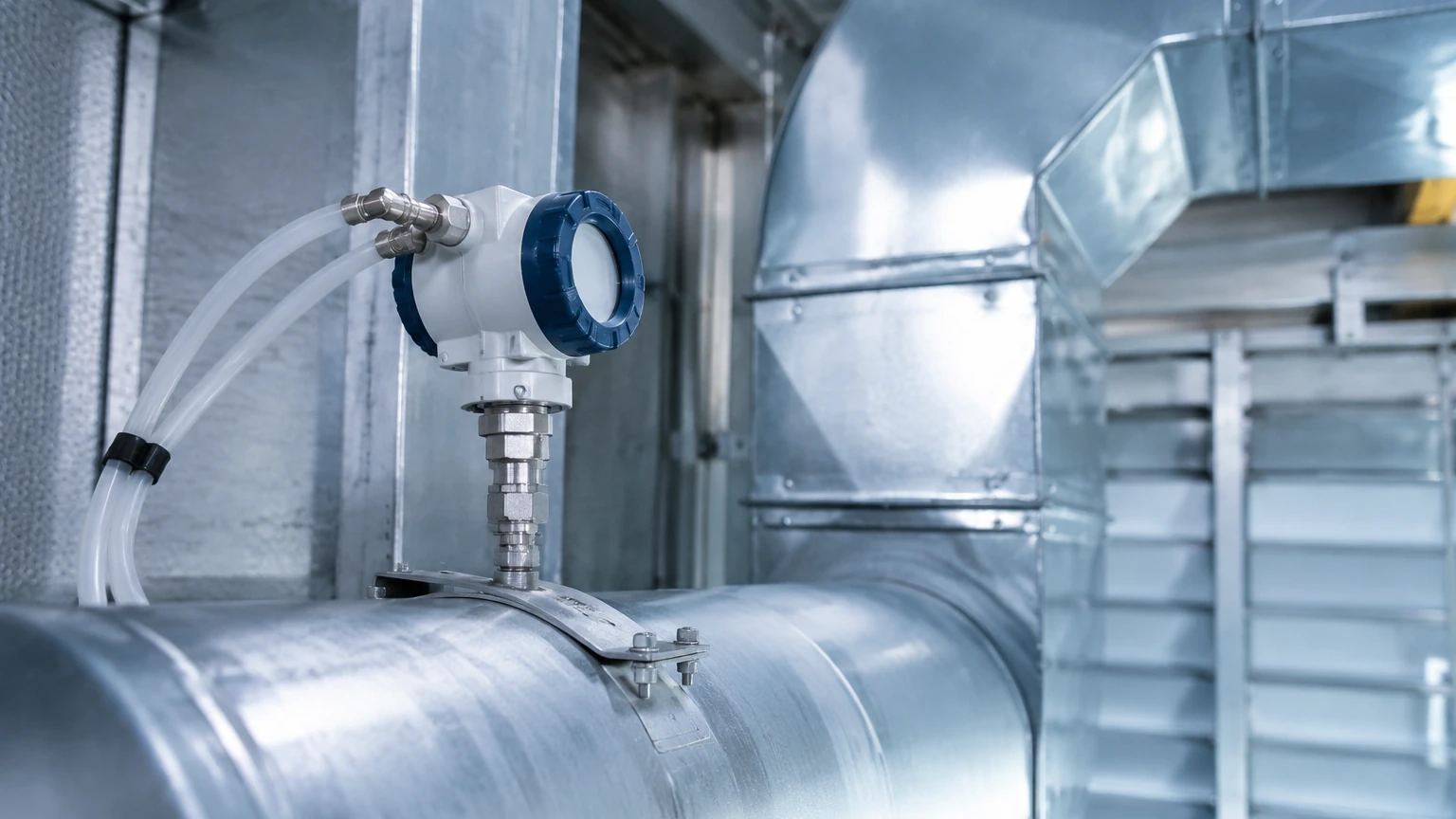
Installation and Calibration Best Practices
Proper installation is as important as the quality of the HVAC pressure transmitter itself. Incorrect placement can lead to "noisy" signals caused by turbulence or air eddies.
1. Siting the Probe
For duct pressure measurements, the sensing probe should be placed in a straight run of ductwork, ideally at least five to ten duct diameters downstream from any elbows, transitions, or fans. This ensures the air profile is laminar and the pressure reading is representative of the actual system state.
2. Orientation Matters
Many low-pressure transmitters are sensitive to gravity. If a sensor is calibrated in a vertical position but installed horizontally, the weight of the internal diaphragm may cause a "zero shift." Always install the unit in the orientation specified by the manufacturer or perform a zero-point calibration after installation.
3. Tubing Considerations
When connecting the transmitter to the process, use high-quality plastic or copper tubing. Ensure there are no kinks or sharp bends. In outdoor installations or areas with high humidity, include a "drip leg" in the tubing to prevent condensation from entering the sensor housing.
4. Zeroing the Sensor
Before commissioning, the transmitter should be zeroed. For differential pressure units, this involves venting both ports to the atmosphere and pressing the zero button or adjusting the potentiometer until the output reads exactly 4 mA or 0 V.
Troubleshooting and Limitations
While modern HVAC pressure transmitters are highly reliable, they are not immune to issues. Understanding these limitations helps in maintaining system performance.
* Clogging: In exhaust systems or environments with high particulate matter, the pressure ports or pitot tubes can become clogged. Regular inspection and the use of filtered probes can mitigate this.
* Temperature Drift: Sensors installed in unconditioned spaces (like rooftops) experience significant temperature swings. Ensure the transmitter has internal temperature compensation or is rated for the ambient environment.
* Long-Term Drift: All sensors drift over time. In critical B2B environments, an annual calibration check against a certified master gauge is recommended to maintain accuracy.
* Media Compatibility: Ensure the wetted materials of the transmitter (the parts that touch the fluid) are compatible with the media. For example, standard air transmitters cannot be used with corrosive gases or liquids.
Frequently Asked Questions (FAQs)
Q: Can I use a water pressure transmitter for air applications?
A: While technically possible if the ranges match, it is not recommended. Water pressure transmitters are designed for higher pressures and may lack the sensitivity required for the low-pressure nuances of air systems. Conversely, air transmitters should never be used with liquids unless explicitly rated for "wet/wet" differential pressure.
Q: What is the difference between Gauge, Absolute, and Differential pressure?
A:
* Gauge Pressure: Measured relative to local atmospheric pressure.
* Absolute Pressure: Measured relative to a perfect vacuum.
* Differential Pressure: The difference in pressure between two distinct points (e.g., before and after a filter).
Q: How often should an HVAC pressure transmitter be calibrated?
A: For standard commercial building applications, every 2 years is usually sufficient. For regulated environments like pharmaceutical manufacturing or healthcare, annual or semi-annual calibration is often mandated.
Conclusion
The HVAC pressure transmitter is a small but mighty component in the infrastructure of modern buildings. By selecting the appropriate sensing technology, adhering to strict installation guidelines, and understanding the specific needs of the application—whether it be air filtration or hydronic balancing—engineers can ensure a system that is both efficient and reliable. For those seeking high-quality industrial measurement solutions, visiting the Main Page of an established manufacturer like Welk provides access to a broad range of instruments designed for the most demanding process environments.