In Line Pressure Sensor
In Line Pressure Sensor
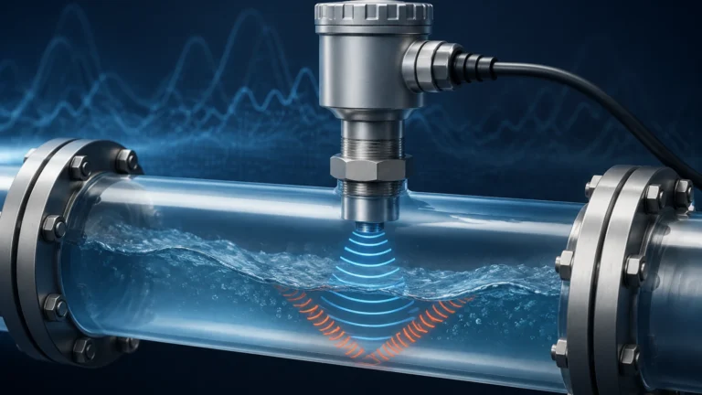
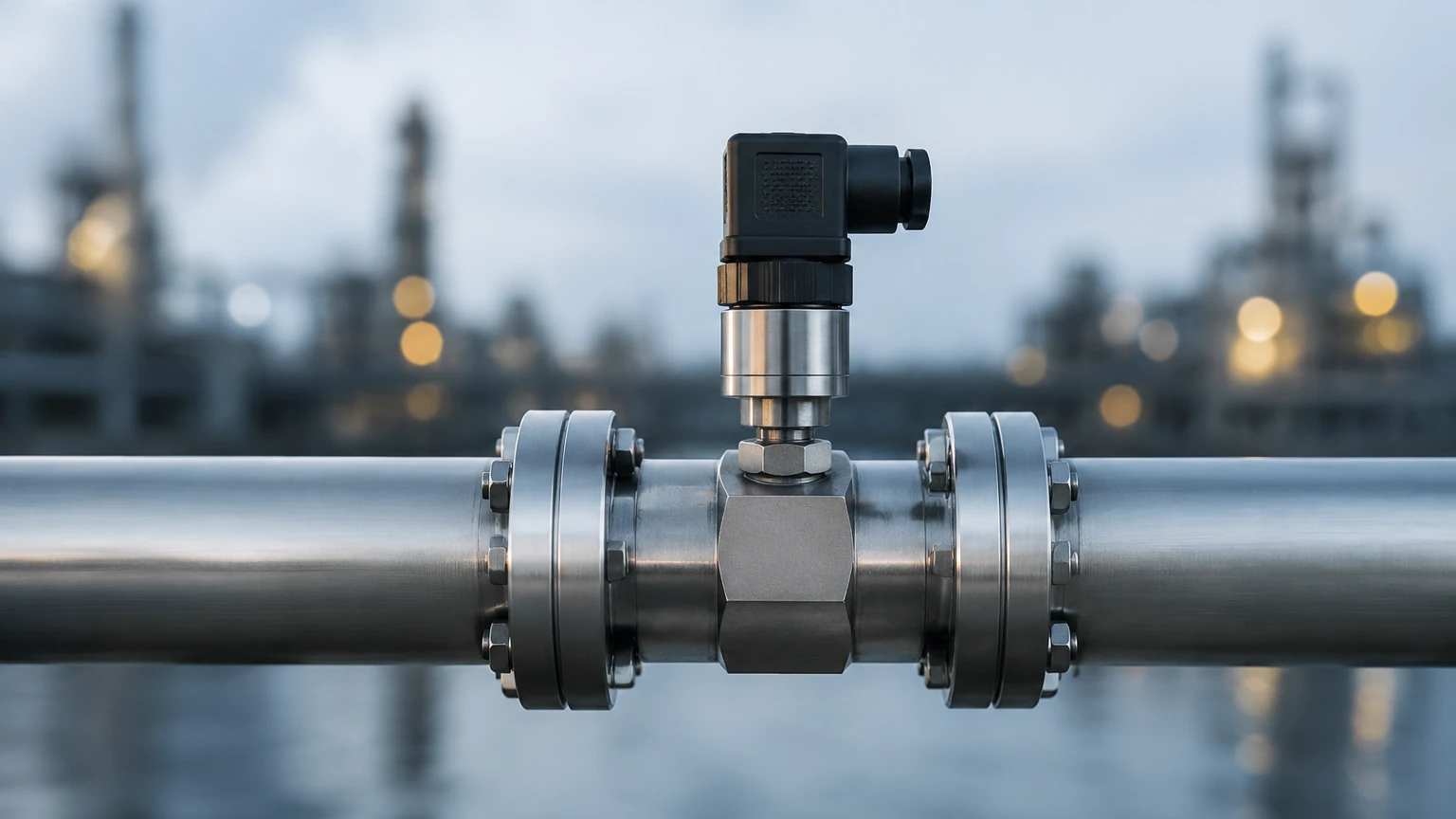
In the landscape of industrial process control, the in line pressure sensor serves as a fundamental component for monitoring, regulating, and securing fluid systems. Unlike submersible or non-contact sensors, an in line pressure sensor is integrated directly into the piping or vessel wall, becoming a physical part of the process boundary. This configuration allows for real-time, continuous measurement of the force exerted by liquids or gases against the internal surfaces of the system.
For engineers and plant managers, selecting the correct pressure instrumentation is critical not only for operational efficiency but also for the structural integrity of the entire facility. This guide explores the technical principles, application strategies, and selection criteria for in-line pressure measurement, particularly in the context of level and flow automation.
Measurement Principles of In Line Pressure Sensors
To choose the right instrument, one must first understand the transducer technology used to convert physical pressure into an electrical signal. Most modern in line pressure sensors utilize one of three primary physical principles.
Piezoresistive Sensors
These sensors utilize a silicon or ceramic diaphragm with integrated resistors. When pressure is applied, the diaphragm deforms, changing the electrical resistance of the material (the piezoresistive effect). This change is measured via a Wheatstone bridge circuit. Piezoresistive sensors are highly sensitive and offer excellent stability, making them the standard for general-purpose industrial applications.
Capacitive Sensors
In a capacitive in line pressure sensor, a sensing diaphragm and a reference electrode form a capacitor. As pressure moves the diaphragm, the distance between the plates changes, resulting in a measurable change in capacitance. These sensors are known for their robustness and high accuracy, especially in low-pressure ranges (below 100 mbar or 1.45 psi). They are also highly resistant to overpressure conditions.
Strain Gauge Sensors
This technology involves bonding a metal foil or thin-film strain gauge to a flexible diaphragm. As the diaphragm flexes under pressure, the strain gauge stretches or compresses, altering its resistance. While often less sensitive than piezoresistive types, strain gauge sensors are exceptionally durable and are preferred for high-pressure hydraulic systems or applications involving significant mechanical shock.
The Relationship Between Pressure and Level Measurement
While an in line pressure sensor measures force per unit area, it is frequently employed as a proxy for liquid level measurement through the principle of hydrostatic pressure. In a vented tank, the pressure at the bottom of the vessel is directly proportional to the height of the liquid column above it, according to the formula:
P = ρ × g × h
Where:
* P is the hydrostatic pressure (Pa or bar).
* ρ (rho) is the density of the liquid (kg/m³).
* g is the local acceleration due to gravity (approx. 9.81 m/s²).
* h is the height of the liquid (m).
By installing an in line pressure sensor at the lowest point of a tank or reservoir, operators can calculate the exact level of the medium. This method is highly effective for water treatment, chemical storage, and oil-and-gas applications where the density of the fluid remains relatively constant. For a deeper look at how these instruments integrate into broader industrial systems, you may review product options and application support on our Main Page.
Key Evaluation Criteria for Selection
Selecting an in line pressure sensor requires a detailed analysis of the process environment. Failure to account for chemical compatibility or thermal dynamics can lead to premature sensor failure or inaccurate data.
Pressure Range and Type
Engineers must define the working pressure range and the required "overpressure" rating. It is standard practice to select a sensor with a range approximately 20-30% higher than the maximum expected process pressure. Additionally, the type of pressure measurement must be specified:
* Gauge Pressure: Measured relative to atmospheric pressure.
* Absolute Pressure: Measured relative to a perfect vacuum.
* Differential Pressure: Measured as the difference between two points in the system (common for filter monitoring and flow measurement).
Media Compatibility
The wetted parts of the sensor—the components that come into direct contact with the fluid—must be chemically resistant. Common materials include:
* 316L Stainless Steel: Standard for water, oils, and mild chemicals.
* Hastelloy C or Tantalum: Required for highly corrosive acids or chlorides.
* Ceramic (Al₂O₃): Excellent for abrasive slurries and aggressive chemicals.
Signal Output and Communication
In modern industrial automation, the sensor must communicate with a PLC (Programmable Logic Controller) or DCS (Distributed Control System). Common outputs include:
* Analog 4-20 mA: The industry standard for long-distance transmission with high noise immunity.
* 0-10 V DC: Common in HVAC and light industrial settings.
* Digital Protocols: HART, Modbus RS485, or Profibus, which allow for remote diagnostics and multi-parameter reporting.
Technical Selection Table
| Feature | Piezoresistive | Ceramic Capacitive | Thin-Film Strain Gauge |
| :— | :— | :— | :— |
| Typical Accuracy | 0.25% to 0.5% FS | 0.1% to 0.2% FS | 0.5% FS |
| Pressure Range | Low to Medium (up to 600 bar) | Very Low to Medium | High (up to 2000+ bar) |
| Temp. Stability | Moderate | High | Excellent |
| Corrosion Resistance | Depends on housing | Excellent (inherent) | High (with proper coating) |
| Best For | General automation | Chemical processing | Hydraulics & Heavy Machinery |
Installation Considerations
Correct installation is as important as selecting the right sensor. Improper mounting can introduce measurement errors or mechanical stress on the sensor diaphragm.
1. Orientation: For liquid applications, the in line pressure sensor should ideally be mounted on the side or bottom of the pipe to ensure the sensing element remains wetted and to prevent air pockets. For gas applications, mounting on the top of the pipe prevents condensate from pooling on the diaphragm.
2. Isolation Valves: Always install a block-and-bleed valve or a needle valve between the process line and the sensor. This allows for safe removal and calibration without shutting down the entire process.
3. Impulse Lines: If the process temperature exceeds the sensor's rated limit (typically above 85°C or 185°F), use a siphon or an elongated impulse line to allow the fluid to cool before reaching the sensing element.
4. Turbulence: Avoid installing sensors immediately downstream of pumps, valves, or elbows. A straight run of pipe (typically 5 to 10 diameters) helps ensure a stable pressure profile.
Common Risks and Limitations
While in line pressure sensors are versatile, they are subject to specific industrial risks:
* Pressure Spikes (Water Hammer): Rapid valve closure can create kinetic energy surges that exceed the sensor's burst pressure. In these environments, pressure snubbers should be used to dampen the shock.
* Cavitation: In high-velocity liquid lines, the formation and collapse of vapor bubbles can erode the sensor diaphragm over time.
* Clogging: In applications involving high solids content or viscous fluids (like wastewater or pulp), standard recessed diaphragms may clog. In these cases, a "flush diaphragm" design is required to prevent buildup.
* Thermal Transients: Rapid changes in process temperature can cause "thermal shock," leading to temporary zero-shifts in the output signal. High-quality sensors include internal temperature compensation to mitigate this effect.
Maintenance and Calibration
To maintain accuracy, in line pressure sensors require periodic calibration. In most industrial settings, an annual calibration cycle is sufficient. This involves comparing the sensor's output against a certified reference standard (deadweight tester or digital pressure calibrator). If the sensor features a HART interface, many adjustments can be performed digitally without removing the unit from the line.
Frequently Asked Questions
Q: Can an in line pressure sensor be used for vacuum measurement?
A: Yes, but you must specify a sensor rated for "compound" pressure or absolute pressure. Standard gauge sensors may not be designed to handle the mechanical pull of a vacuum on the diaphragm.
Q: What is the difference between a pressure transducer and a pressure transmitter?
A: While the terms are often used interchangeably, a transducer typically provides a raw voltage output (e.g., mV/V), whereas a transmitter includes signal conditioning electronics to provide a standardized industrial output like 4-20 mA.
Q: How do I handle measurement in hygienic applications?
A: For food, beverage, or pharmaceutical industries, you must use an in line pressure sensor with a sanitary connection (such as a Tri-Clamp) and an internal fill fluid that is food-grade (e.g., glycerin or mineral oil) to ensure no contamination occurs if the diaphragm ruptures.
Conclusion
The in line pressure sensor is a cornerstone of industrial monitoring. By understanding the underlying physics of piezoresistive and capacitive sensing, and by carefully matching material specifications to the process media, engineers can ensure long-term reliability. Whether used for direct pressure monitoring or indirect level measurement, these instruments provide the data necessary for safe and efficient industrial automation. For those seeking specific hardware configurations or technical consultation, Welk provides a range of solutions tailored to water treatment, chemical processing, and general industrial automation.