E&h Promag 400
E&h Promag 400
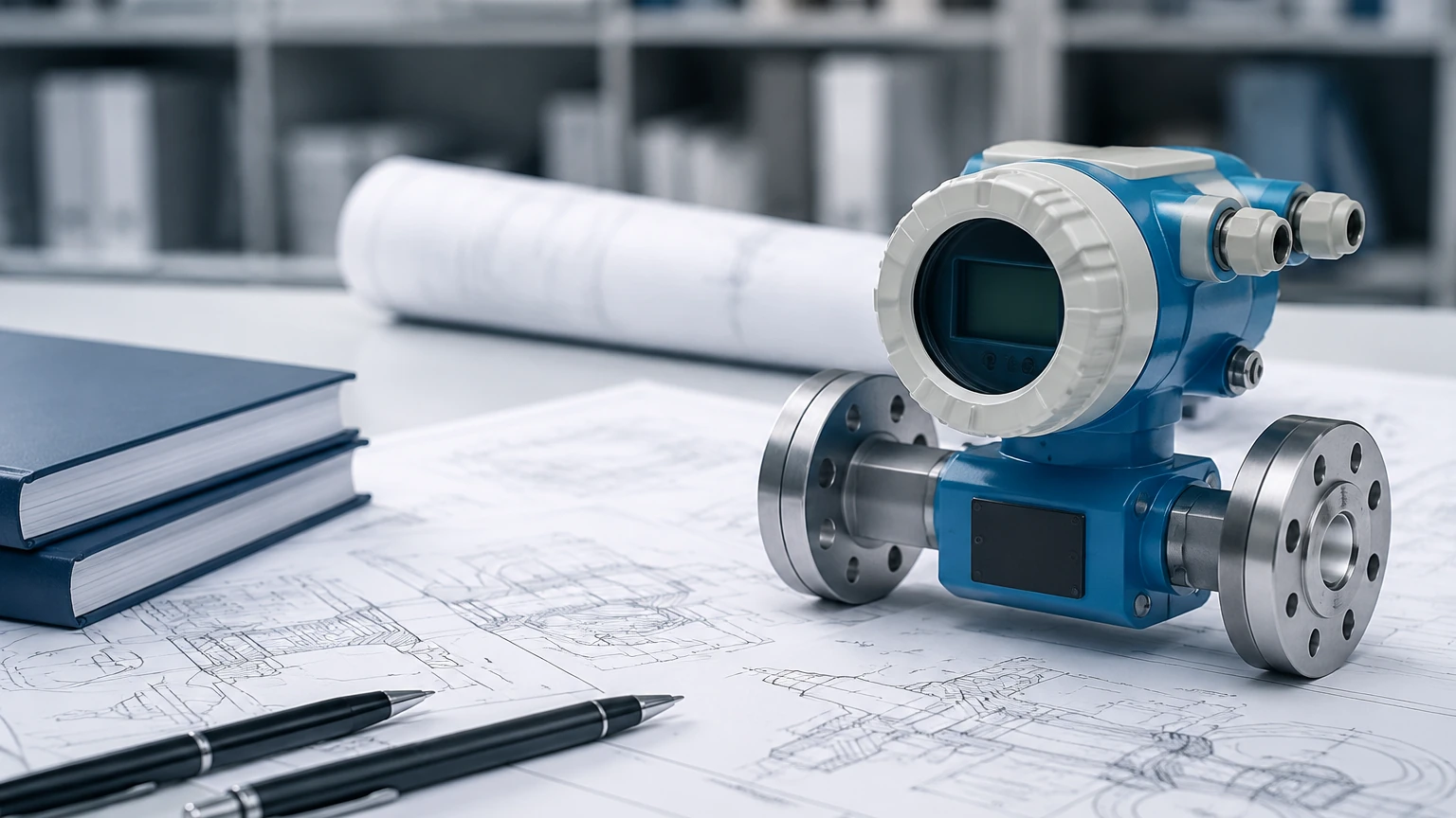
In the landscape of industrial liquid management, the E&H Promag 400 stands as a foundational instrument for flow measurement, particularly within the water and wastewater sectors. As a dedicated electromagnetic flowmeter transmitter, the 400 series is designed to pair with various sensors—most notably the Promag W and Promag L—to provide a robust solution for conductive liquid measurement. This article provides a technical overview of the Promag 400, its operating principles, selection criteria, and installation requirements for engineering professionals.
Measurement Principles of Electromagnetic Flowmeters
Before evaluating the specific features of the Promag 400, it is essential to understand the underlying physics that govern its operation. Electromagnetic flowmeters operate based on Faraday’s Law of Induction. This principle states that a conductor moving through a magnetic field produces an electrical voltage.
In the context of the Promag 400, the "conductor" is the process liquid itself. The meter’s sensor contains a set of electromagnetic coils that generate a constant magnetic field across the cross-section of the measuring pipe. As the conductive liquid flows through this field, a voltage is induced. This voltage is directly proportional to the velocity of the liquid flow. Two electrodes, typically mounted flush with the pipe wall, pick up this induced voltage and transmit it to the Promag 400 transmitter.
The mathematical relationship is expressed as:
E = B · v · d
Where:
* E is the induced voltage.
* B is the magnetic field strength.
* v is the average flow velocity.
* d is the distance between the electrodes (pipe diameter).
Because the magnetic field strength and the pipe diameter are constant, the voltage is a linear representation of the flow velocity. The Promag 400 transmitter then converts this signal into a standardized output, such as 4-20 mA, pulse, or a digital communication protocol. It is important to note that this technology requires a minimum liquid conductivity, typically >5 μS/cm, to function accurately.
Key Features of the Promag 400 Transmitter
The Promag 400 is categorized as a "specialist" transmitter for the water industry. Unlike general-purpose transmitters, it incorporates specific software and hardware features tailored for municipal and industrial water cycles.
Digital Integration and Web Server
One of the defining characteristics of the 400 series is its integrated web server. This allows technicians to access device data, configuration parameters, and diagnostics using a standard web browser on a laptop or tablet, without the need for specialized proprietary software or handheld communicators. This is particularly useful in remote water treatment facilities where ease of access is critical.
Heartbeat Technology
To reduce the need for manual verification and physical removal of the meter, the Promag 400 utilizes Heartbeat Technology. This is an internal diagnostic suite that continuously monitors the health of the sensor and transmitter. It provides documented proof that the device is performing within its original specifications, which is vital for regulatory compliance in drinking water applications.
Communication Protocols
The transmitter supports a wide array of industrial communication standards, ensuring compatibility with modern SCADA and PLC systems. These include:
* HART
* Modbus RS485
* EtherNet/IP
* PROFINET
Practical Selection Criteria
Choosing the correct configuration for a Promag 400 system requires an assessment of the sensor type, liner material, and electrode material. The 400 transmitter is most commonly paired with the Promag W sensor (for versatile water applications) or the Promag L (for weight-optimized applications with lap-joint flanges).
Selection Table: Sensor and Liner Options
| Feature | Promag W (with 400) | Promag L (with 400) |
| :— | :— | :— |
| Primary Application | Water, Wastewater, Utilities | Water, Wastewater (Weight-sensitive) |
| Nominal Diameter | DN 25 to 3000 (1" to 120") | DN 25 to 2400 (1" to 90") |
| Liner Materials | Polyurethane, Hard Rubber, PTFE | Polyurethane, Hard Rubber |
| Standard Accuracy | ±0.5% (Optional ±0.2%) | ±0.5% (Optional ±0.2%) |
| Process Temperature | -20 to +80 °C (-4 to +176 °F) | -20 to +90 °C (-4 to +194 °F) |
| Approvals | Drinking water (NSF 61, KTW, etc.) | Drinking water, Custody transfer |
Material Considerations
* Polyurethane: Best for non-corrosive water and abrasive slurries. It offers high resistance to wear.
* Hard Rubber: The standard choice for large-diameter water transport and wastewater treatment.
* PTFE: Required for applications involving chemicals or high-temperature cleaning cycles, though less common in standard water applications.
Installation Considerations
For an electromagnetic flowmeter like the Promag 400 to provide accurate data, the installation must adhere to specific hydraulic and electrical requirements. Incorrect installation is the leading cause of measurement drift and signal noise.
Straight Pipe Runs (U0D0 Feature)
Traditionally, electromagnetic meters require a straight run of pipe upstream (typically 5x pipe diameter) and downstream (2x pipe diameter) to ensure a stable flow profile. However, some versions of the Promag W 400 are available with a "0 x DN" (U0D0) configuration. This allows the meter to be installed directly after an elbow or T-junction without loss of accuracy, which is a significant advantage in cramped pump stations or retrofitted facilities.
Orientation and Filling
The measuring tube must always be full of liquid. If the pipe is partially empty, the meter will read incorrectly or fail to provide a signal.
* Vertical Installation: The preferred orientation is a vertical pipe with the flow moving upwards. This ensures the pipe is full and prevents air bubbles from accumulating at the electrodes.
* Horizontal Installation: If the pipe is horizontal, the sensor should be installed in a low point of the piping system. The electrode axis must be horizontal to prevent air bubbles (at the top) or sediment (at the bottom) from insulating the electrodes.
Grounding
Since the meter measures millivolts of induced potential, it is highly sensitive to electrical noise in the piping system. The process liquid, the sensor, and the transmitter must be at the same electrical potential. This is achieved through grounding. In plastic or lined pipes, grounding rings or extra grounding electrodes are necessary to establish a reliable electrical connection with the fluid.
Limitations and Common Risks
While the Promag 400 is a highly reliable instrument, it is not suitable for every application. Engineers should be aware of the following limitations:
1. Non-Conductive Liquids: The meter cannot measure hydrocarbons (oil, diesel), distilled water, or gases. If the conductivity drops below 5 μS/cm, the signal will be lost.
2. Vacuum Sensitivity: In systems where a vacuum may occur (e.g., downstream of a pump failure), certain liners like PTFE can collapse or peel away from the pipe wall. Hard rubber or polyurethane liners are generally more resistant to vacuum pressures.
3. Solid Buildup: If the process liquid contains fats, oils, or greases (FOG), a film can build up over the electrodes. This acts as an insulator and causes the meter to under-read. Regular cleaning or the use of "bullet-head" electrodes may be required in high-grease wastewater applications.
4. Magnetic Interference: High-power motors or variable frequency drives (VFDs) located too close to the sensor can create electromagnetic interference. Shielded cables and proper separation are required.
Integration with Level Measurement
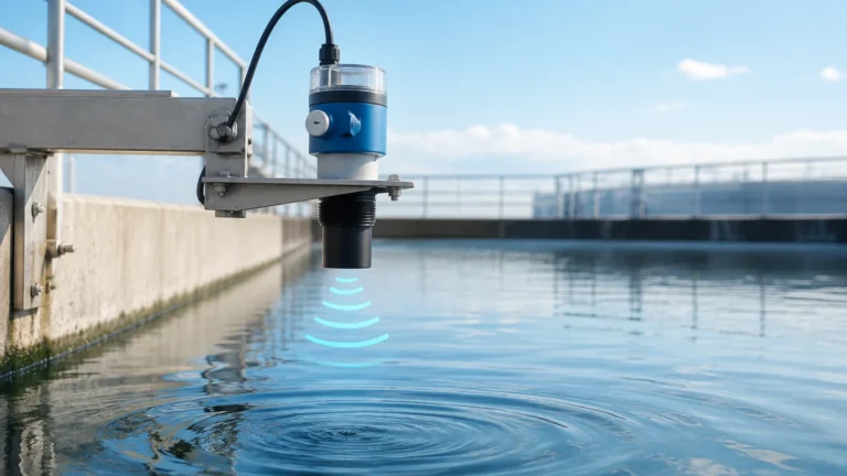
In many industrial processes, flow measurement is only one part of the equation. For comprehensive tank management and process automation, flow data from instruments like the Promag 400 is often integrated with level measurement data. For example, in a water storage reservoir, the flowmeter tracks the volume entering and leaving the system, while a radar or ultrasonic level sensor monitors the total volume currently in storage.
This synergy allows for mass balance calculations and leak detection. If the level in a tank is dropping faster than the outflow measured by the Promag 400, it indicates a potential leak in the infrastructure. For professionals seeking to optimize their entire measurement loop, reviewing a variety of Main Page resources can help in selecting the right combination of level and flow technologies.
Frequently Asked Questions (FAQs)
Q: Can the Promag 400 measure flow in both directions?
A: Yes, electromagnetic meters are inherently bi-directional. The Promag 400 can be configured to track forward and reverse flow separately, which is useful for distribution networks where flow direction may change based on demand.
Q: How often does the Promag 400 need to be calibrated?
A: In many water applications, the meter can operate for several years without physical recalibration. However, regulatory requirements often dictate a verification interval. The Heartbeat Technology feature allows for in-situ verification, which can extend the time between formal laboratory calibrations.
Q: What is the maximum cable length for remote versions?
A: For remote installations where the transmitter is mounted away from the sensor, the maximum cable length is typically 200 meters (approx. 650 feet), depending on the conductivity of the liquid. Higher conductivity allows for longer cable runs.
Q: Does the Promag 400 require a specific power supply?
A: The transmitter is available in various power configurations, including wide-range AC (100 to 240 V) and DC (24 V) options, making it adaptable to most industrial power grids.
Conclusion
The E&H Promag 400 is a specialized tool designed to meet the rigorous demands of the water industry. By leveraging Faraday’s Law and modern digital features like Heartbeat Technology and integrated web servers, it provides a balance of accuracy and ease of maintenance. When selecting this instrument, engineers must carefully consider the liner materials and installation geometry to ensure long-term performance. For broader application support and to explore complementary measurement technologies, users are encouraged to visit the Main Page to review product options and application support.