Industrial Water Treatment
Industrial Water Treatment
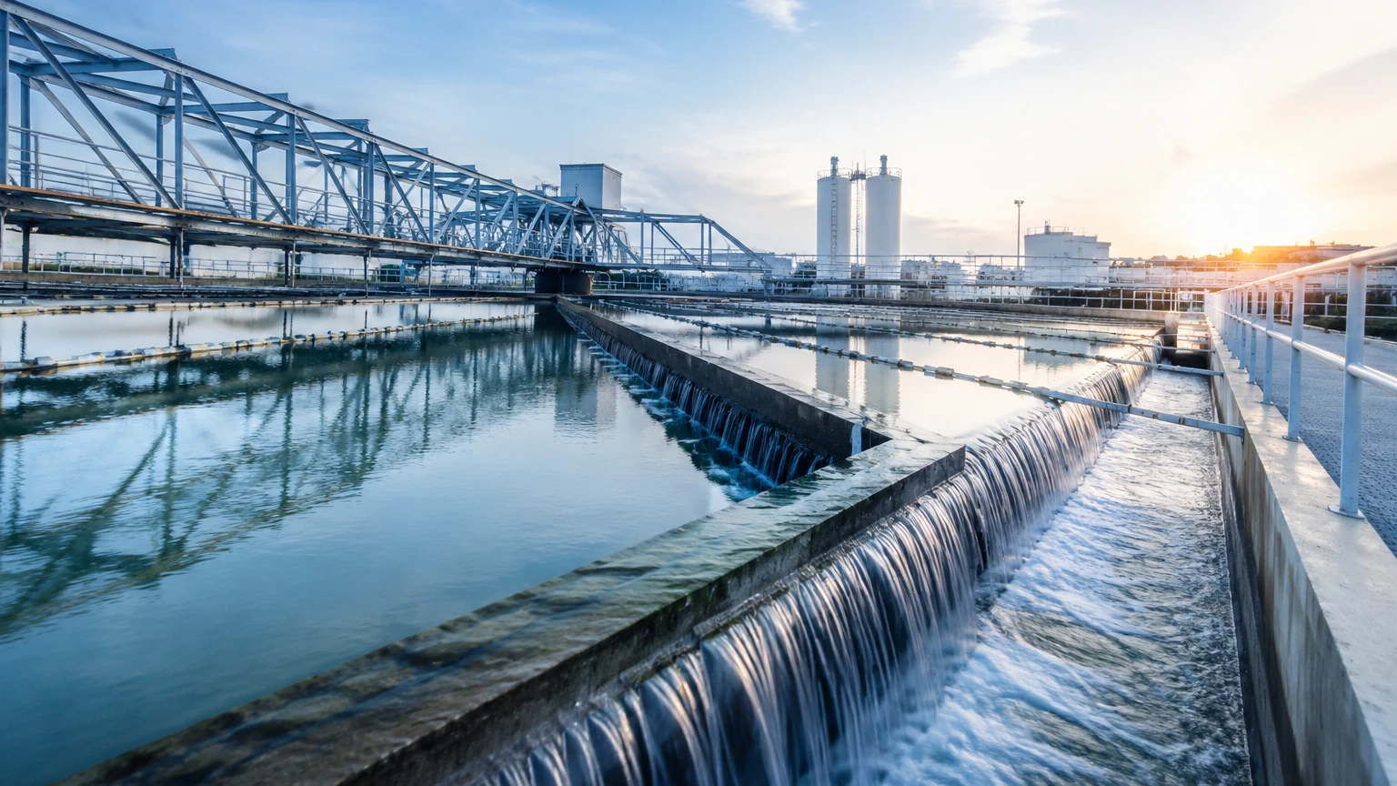
Industrial water treatment encompasses the complex processes used to optimize water quality for specific industrial end-uses, such as manufacturing, thermal power generation, and chemical processing. Effective management of these systems is not only a matter of environmental compliance but also a critical factor in operational efficiency and equipment longevity. At the heart of these processes lies the need for precise monitoring, where level measurement instruments ensure that tanks do not overflow, pumps do not run dry, and chemical dosing remains accurate.
In the context of industrial water treatment, selecting the correct instrumentation requires an understanding of the physical properties of the water (e.g., turbidity, temperature, and chemical composition) and the mechanical constraints of the storage or processing vessel. As a professional manufacturer, Welk provides a range of sensors designed to meet these rigorous demands.
Core Measurement Principles for Water Systems
Before selecting a device for an industrial water treatment application, it is essential to understand the underlying physics of the most common measurement technologies. Each principle offers distinct advantages depending on the environment.
Ultrasonic Level Measurement
Ultrasonic sensors operate on the Time-of-Flight (ToF) principle. The device’s transducer emits high-frequency sound pulses that travel through the air, reflect off the liquid surface, and return to the sensor. The distance is calculated based on the time interval and the speed of sound ($v \approx 343$ m/s at 20°C).
In industrial water treatment, ultrasonic sensors are favored for their non-contact nature, making them ideal for wastewater basins or open channels. However, they are sensitive to air temperature fluctuations, heavy foam, and surface turbulence, which can scatter the sound waves.
Radar Level Measurement (FMCW and Pulse)
Radar sensors use electromagnetic waves rather than sound. Frequency Modulated Continuous Wave (FMCW) radar is increasingly common in the industry. These devices emit a continuous signal with a changing frequency; the difference between the emitted and received frequency is proportional to the distance.
Radar is highly effective in industrial water treatment because it is unaffected by vacuum, pressure, or temperature changes in the vapor space. High-frequency radar (such as 80GHz) allows for a narrow beam angle, which is useful in tanks with internal obstructions like agitators or ladders.
Hydrostatic Level Measurement
This principle relies on the relationship between liquid height ($h$) and the pressure ($P$) exerted at the bottom of the vessel: $P = \rho gh$, where $\rho$ is the density of the fluid and $g$ is gravity. A pressure transmitter or submersible transducer measures the head pressure of the water column. This method is highly reliable for deep wells or large reservoirs where non-contact sensors might struggle with range or signal dispersion.
Magnetic Level Gauges
Magnetic gauges utilize a float containing a permanent magnet. As the liquid level changes, the float moves a series of magnetic flags or a transmitter outside the chamber. This provides a clear visual indication and a secondary electronic signal, often used in boiler feed water systems or high-pressure tanks where electronic-only sensors require a mechanical backup.
Technology Selection for Specific Water Treatment Stages
Industrial water treatment is rarely a single-step process. Different stages require tailored instrumentation to handle varying levels of contamination and chemical aggression.
Raw Water Intake and Pre-treatment
Raw water often contains debris, silt, and varying biological loads. For large intake basins, ultrasonic sensors are typically used due to their cost-effectiveness over wide areas. If the intake is subject to heavy fog or steam, non-contact radar is the preferred alternative to ensure signal penetration. For more information on equipment suitable for these stages, engineers can visit the Main Page to review product options and application support.
Chemical Dosing and Softening
Water softening and demineralization involve the storage of corrosive chemicals such as hydrochloric acid (HCl), sodium hydroxide (NaOH), or various flocculants. Level sensors in these tanks must be constructed from chemically resistant materials like PTFE or PVDF. Radar sensors are ideal here because they can measure through plastic tank roofs or be sealed within a protective housing, preventing the electronics from being exposed to corrosive vapors.
Clarification and Sedimentation
In clarifiers, the goal is to separate solids from the water. Monitoring the sludge blanket level is critical. While ultrasonic sensors can monitor the surface level of the water, specialized hydrostatic sensors are often used to monitor the density and height of the accumulated sludge at the bottom of the cone.
Filtration and Reverse Osmosis (RO)
Filtration stages often involve pressurized vessels. Hydrostatic pressure transmitters are the standard for monitoring filter bed levels and differential pressure across membranes. Accurate level control in RO surge tanks ensures a steady flow to high-pressure pumps, preventing cavitation and membrane damage.
Practical Selection Table for Engineering Design
The following table provides a comparison of the primary technologies used in industrial water treatment to assist in the initial selection process.
| Technology | Typical Range | Accuracy | Best For | Limitations |
| :— | :— | :— | :— | :— |
| Ultrasonic | 0.25m – 15m (0.8ft – 49ft) | ±0.25% of range | Open channels, sumps, wastewater | Affected by foam, wind, and temperature |
| 80GHz Radar | 0.1m – 120m (0.3ft – 393ft) | ±1mm (0.04in) | Narrow tanks, chemical dosing, steam | Higher initial cost than ultrasonic |
| Hydrostatic | 0.5m – 200m (1.6ft – 656ft) | ±0.1% to 0.5% | Deep wells, pressurized tanks | Sensitive to changes in liquid density |
| Magnetic Gauge| 0.3m – 6m (1ft – 20ft) | ±5mm (0.2in) | Boiler water, high-pressure vessels | Requires bypass piping; mechanical wear |
Installation Guidelines and Technical Limitations
Successful implementation of level measurement in industrial water treatment depends heavily on correct installation. Failure to account for the physical environment can lead to signal loss or false readings.
1. Beam Angle and Obstructions: For radar and ultrasonic sensors, the "beam angle" defines the cone-shaped area where the signal travels. If this cone hits a ladder, pipe, or agitator, it will create a "false echo." Modern sensors allow for "false echo suppression" via software, but it is best practice to install the sensor at least 200mm (8in) away from the tank wall and clear of any internal structures.
2. Dead Zones (Blocking Distance): All ToF sensors have a minimum distance they cannot measure, typically 0.1m to 0.5m (4in to 20in) from the sensor face. If the water level rises into this zone, the sensor will provide an error or a locked reading. Mounting the sensor on a nozzle or standpipe can help move the dead zone above the maximum fill level.
3. Foam Management: Heavy, thick foam acts as an insulator for ultrasonic waves and can absorb radar signals. In such cases, a guided wave radar (GWR) using a probe or a hydrostatic sensor is more reliable, as they are not affected by surface foam.
4. Stilling Wells: In tanks with high turbulence or surface agitation, installing the sensor inside a stilling well (a vertical pipe) can provide a calm surface for measurement. This is particularly useful for radar and ultrasonic technologies in mixing tanks.
Frequently Asked Questions (FAQ)
Q: Can I use an ultrasonic sensor for boiling water?
A: Generally, no. Heavy steam and high temperatures significantly change the speed of sound, leading to large errors. Additionally, condensation on the transducer face can block the signal. Radar is the superior choice for high-temperature water or steam applications.
Q: How do I handle varying density in hydrostatic measurement?
A: Hydrostatic sensors assume a constant density. If the water density changes (e.g., due to varying salinity or temperature), the level reading will drift. If density varies significantly, a dual-sensor differential pressure setup or a non-contact radar should be used instead.
Q: What maintenance is required for water level sensors?
A: Non-contact sensors like radar require very little maintenance. Ultrasonic sensors may need occasional cleaning if grease or biological growth accumulates on the transducer. Submersible hydrostatic sensors should be checked periodically for clogging of the pressure port or moisture in the vent tube.
Q: Is 80GHz radar always better than 26GHz radar for water?
A: 80GHz radar offers a narrower beam and better resolution, making it better for small tanks or tanks with many internals. However, 26GHz radar is often sufficient for large, open basins and can be more cost-effective for simple industrial water treatment tasks.
Conclusion
Selecting the right level measurement technology is a foundational step in designing a robust industrial water treatment system. By understanding the principles of radar, ultrasonic, and hydrostatic measurement, engineers can ensure long-term accuracy and safety. Whether managing raw water intake or complex chemical dosing, the choice of instrument must align with the specific physical and chemical challenges of the application. For comprehensive technical specifications and to explore the full range of industrial level solutions, visit the Main Page for professional guidance and product support.